1_H24维修手册.pdf - 第210页
E d i ti o n 5 . 0 H 24 H ead R ep ai r T r ai n i n g T ext f o r S er vi ce E n g i n e e r s I PS C a m e r a p o s i ti o n a d j u s tm e n t fo r H 2 4 h e a d u s i n g h e a d b e n c h 5. P r es s t he up per bu…
Edition 5.0 H24 Head Repair Training Text for Service Engineers
IPS Camera position adjustment for H24 head using head bench
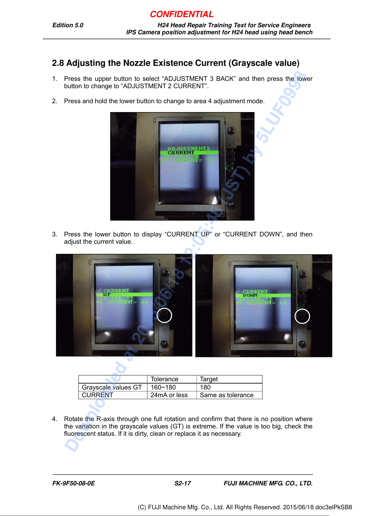
2.8 Adjusting the Nozzle Existence Current (Grayscale value)
1. Press the upper button to select “ADJUSTMENT 3 BACK” and then press the lower
button to change to “ADJUSTMENT 2 CURRENT”.
2. Press and hold the lower button to change to area 4 adjustment mode.
3. Press the lower button to display “CURRENT UP” or “CURRENT DOWN”, and then
adjust the current value.
4. Rotate the R-axis through one full rotation and confirm that there is no position where
the variation in the grayscale values (GT) is extreme. If the value is too big, check the
fluorescent status. If it is dirty, clean or replace it as necessary.
Tolerance
Target
Grayscale values GT
160~180
180
CURRENT
24mA or less
Same as tolerance
FK-9F50-08-0E S2-17 FUJI MACHINE MFG. CO., LTD.
CONFIDENTIAL
Downloaded at 2015/06/18 12:05:48 (JST) by 5LUF0998
(C) FUJI Machine Mfg. Co., Ltd. All Rights Reserved. 2015/06/18 doc3elPkSB8
Edition 5.0 H24 Head Repair Training Text for Service Engineers
IPS Camera position adjustment for H24 head using head bench
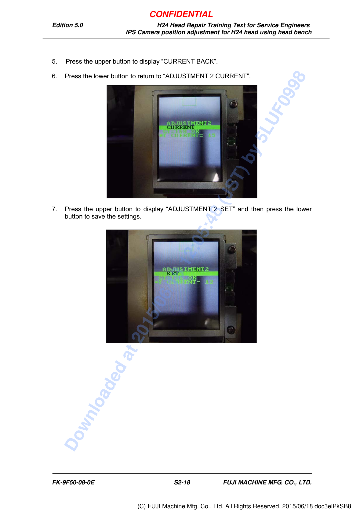
5. Press the upper button to display “CURRENT BACK”.
6. Press the lower button to return to “ADJUSTMENT 2 CURRENT”.
7. Press the upper button to display “ADJUSTMENT 2 SET” and then press the lower
button to save the settings.
FK-9F50-08-0E S2-18 FUJI MACHINE MFG. CO., LTD.
CONFIDENTIAL
Downloaded at 2015/06/18 12:05:48 (JST) by 5LUF0998
(C) FUJI Machine Mfg. Co., Ltd. All Rights Reserved. 2015/06/18 doc3elPkSB8
Edition 5.0 H24 Head Repair Training Text for Service Engineers
IPS Camera position adjustment for H24 head using head bench
2.9 Checking the Nozzle Existence Field of Vision
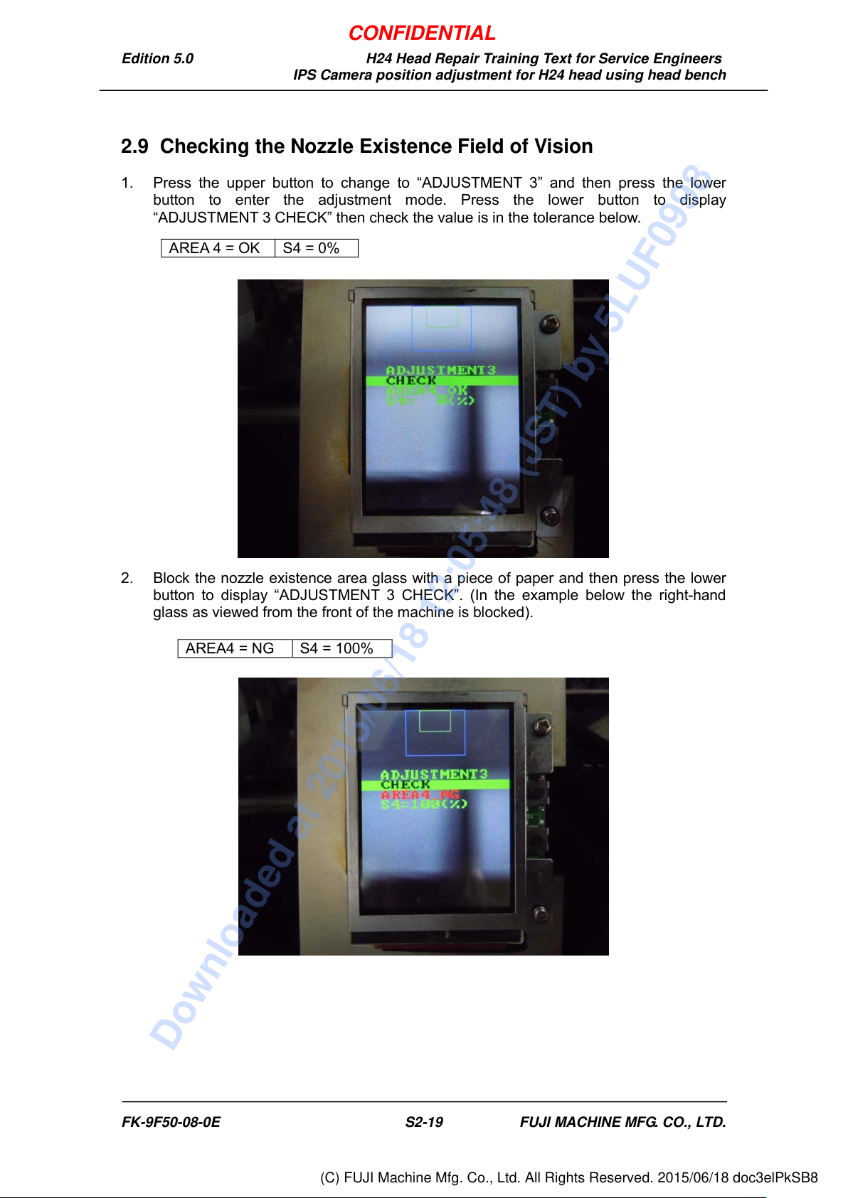
1. Press the upper button to change to “ADJUSTMENT 3” and then press the lower
button to enter the adjustment mode. Press the lower button to display
“ADJUSTMENT 3 CHECK” then check the value is in the tolerance below.
2. Block the nozzle existence area glass with a piece of paper and then press the lower
button to display “ADJUSTMENT 3 CHECK”. (In the example below the right-hand
glass as viewed from the front of the machine is blocked).
AREA 4 = OK
S4 = 0%
AREA4 = NG
S4 = 100%
FK-9F50-08-0E S2-19 FUJI MACHINE MFG. CO., LTD.
CONFIDENTIAL
Downloaded at 2015/06/18 12:05:48 (JST) by 5LUF0998
(C) FUJI Machine Mfg. Co., Ltd. All Rights Reserved. 2015/06/18 doc3elPkSB8