1_H24维修手册.pdf - 第86页
E d i ti o n 5 .0 H 24 H ead R ep ai r T r ai n i n g T e xt f o r S er v i ce E n g i n eer s R e p l a c i n g a n d A d j u s ti n g th e S te p p i n g M o to r 4. T he f ol l ow i n g w i nd ow ope ns . S el ec t “ …
Edition 5.0 H24 Head Repair Training Text for Service Engineers
Replacing and Adjusting the Stepping Motor
7.3 Setting the Step Motor Origin
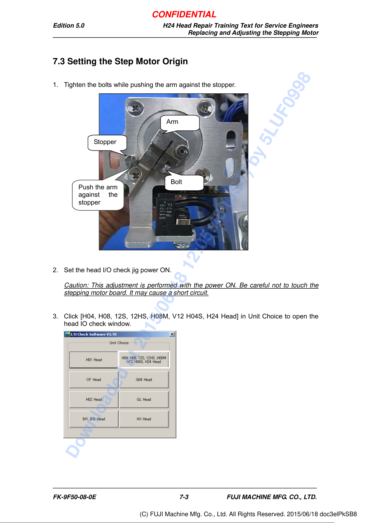
1. Tighten the bolts while pushing the arm against the stopper.
2. Set the head I/O check jig power ON.
Caution: This adjustment is performed with the power ON. Be careful not to touch the
stepping motor board. It may cause a short circuit.
3. Click [H04, H08, 12S, 12HS, H08M, V12 H04S, H24 Head] in Unit Choice to open the
head IO check window.
Push the arm
against the
stopper
Bolt
Arm
Stopper
FK-9F50-08-0E 7-3 FUJI MACHINE MFG. CO., LTD.
CONFIDENTIAL
Downloaded at 2015/06/18 12:05:48 (JST) by 5LUF0998
(C) FUJI Machine Mfg. Co., Ltd. All Rights Reserved. 2015/06/18 doc3elPkSB8
Edition 5.0 H24 Head Repair Training Text for Service Engineers
Replacing and Adjusting the Stepping Motor
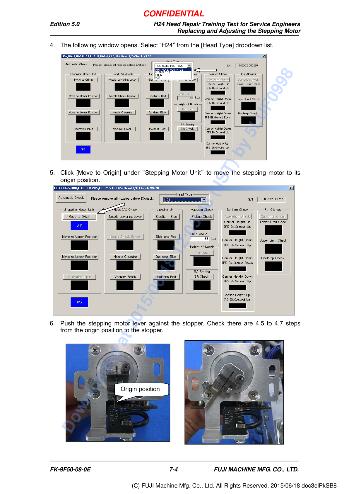
4. The following window opens. Select “H24” from the [Head Type] dropdown list.
5. Click [Move to Origin] under “Stepping Motor Unit” to move the stepping motor to its
origin position.
6. Push the stepping motor lever against the stopper. Check there are 4.5 to 4.7 steps
from the origin position to the stopper.
Origin position
FK-9F50-08-0E 7-4 FUJI MACHINE MFG. CO., LTD.
CONFIDENTIAL
Downloaded at 2015/06/18 12:05:48 (JST) by 5LUF0998
(C) FUJI Machine Mfg. Co., Ltd. All Rights Reserved. 2015/06/18 doc3elPkSB8
Edition 5.0 H24 Head Repair Training Text for Service Engineers
Replacing and Adjusting the Stepping Motor
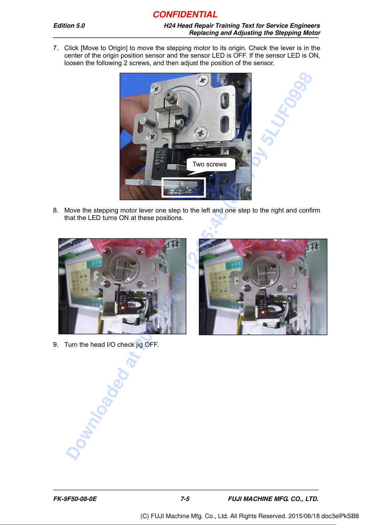
7. Click [Move to Origin] to move the stepping motor to its origin. Check the lever is in the
center of the origin position sensor and the sensor LED is OFF. If the sensor LED is ON,
loosen the following 2 screws, and then adjust the position of the sensor.
8. Move the stepping motor lever one step to the left and one step to the right and confirm
that the LED turns ON at these positions.
9. Turn the head I/O check jig OFF.
Two screws
FK-9F50-08-0E 7-5 FUJI MACHINE MFG. CO., LTD.
CONFIDENTIAL
Downloaded at 2015/06/18 12:05:48 (JST) by 5LUF0998
(C) FUJI Machine Mfg. Co., Ltd. All Rights Reserved. 2015/06/18 doc3elPkSB8