1_H24维修手册.pdf - 第194页
E d i ti o n 5 .0 H 24 H ead R ep ai r T r ai n i n g T ext f o r S er vi ce E n g i n e e r s I PS C a m e r a p o s i ti o n a d j u s tm e n t fo r H 2 4 h e a d u s i n g h e a d b e n c h 2 . 2 P r e p a r a t i o n…
Edition 5.0 H24 Head Repair Training Text for Service Engineers
IPS Camera position adjustment for H24 head using head bench
Supplement 2 –IPS Camera Position Adjustment for
H24 Head Using Head Bench
This procedure is written for H24 head.
NOTE: The servo power is ON during this measurement. Please exercise special caution
during this measurement.
Camera position adjustment, current value (grayscale value)
adjustment and area check
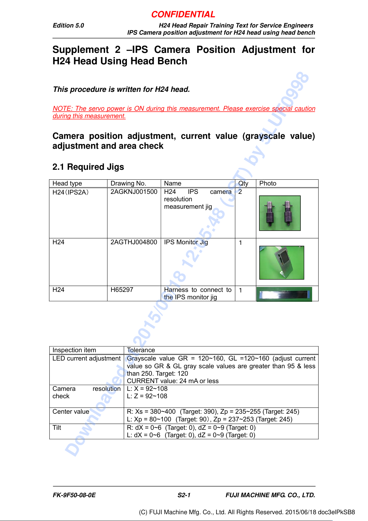
2.1 Required Jigs
Head type
Drawing No.
Name
Qty
Photo
H24
(
IPS2A
)
2AGKNJ001500
H24 IPS camera
resolution
measurement jig
2
H24
2AGTHJ004800
IPS Monitor Jig
1
H24
H65297
Harness to connect to
the IPS monitor jig
1
Inspection item
Tolerance
LED current adjustment
Grayscale value GR = 120~160, GL =120~160 (adjust current
value so GR & GL gray scale values are greater than 95 & less
than 250. Target: 120
CURRENT value: 24 mA or less
Camera resolution
check
L: X = 92~108
L: Z = 92~108
Center value
R: Xs = 380~400
(Target: 390), Zp = 235~255 (Target: 245)
L: Xp = 80~100
(Target: 90
)
, Zp = 237~253 (Target: 245)
Tilt
R: dX = 0~6 (Target: 0), dZ = 0~9 (Target: 0)
L: dX = 0~6
(Target: 0), dZ = 0~9 (Target: 0)
FK-9F50-08-0E S2-1 FUJI MACHINE MFG. CO., LTD.
CONFIDENTIAL
Downloaded at 2015/06/18 12:05:48 (JST) by 5LUF0998
(C) FUJI Machine Mfg. Co., Ltd. All Rights Reserved. 2015/06/18 doc3elPkSB8
Edition 5.0 H24 Head Repair Training Text for Service Engineers
IPS Camera position adjustment for H24 head using head bench
2.2 Preparation On the Head bench
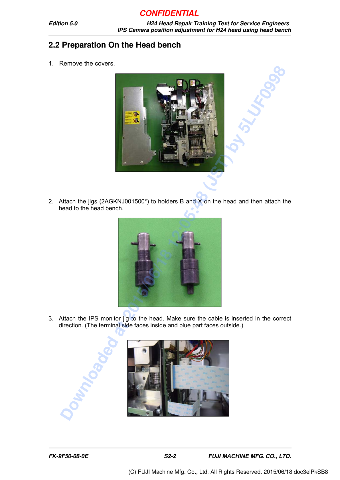
1. Remove the covers.
2. Attach the jigs (2AGKNJ001500*) to holders B and X on the head and then attach the
head to the head bench.
3. Attach the IPS monitor jig to the head. Make sure the cable is inserted in the correct
direction. (The terminal side faces inside and blue part faces outside.)
FK-9F50-08-0E S2-2 FUJI MACHINE MFG. CO., LTD.
CONFIDENTIAL
Downloaded at 2015/06/18 12:05:48 (JST) by 5LUF0998
(C) FUJI Machine Mfg. Co., Ltd. All Rights Reserved. 2015/06/18 doc3elPkSB8
Edition 5.0 H24 Head Repair Training Text for Service Engineers
IPS Camera position adjustment for H24 head using head bench
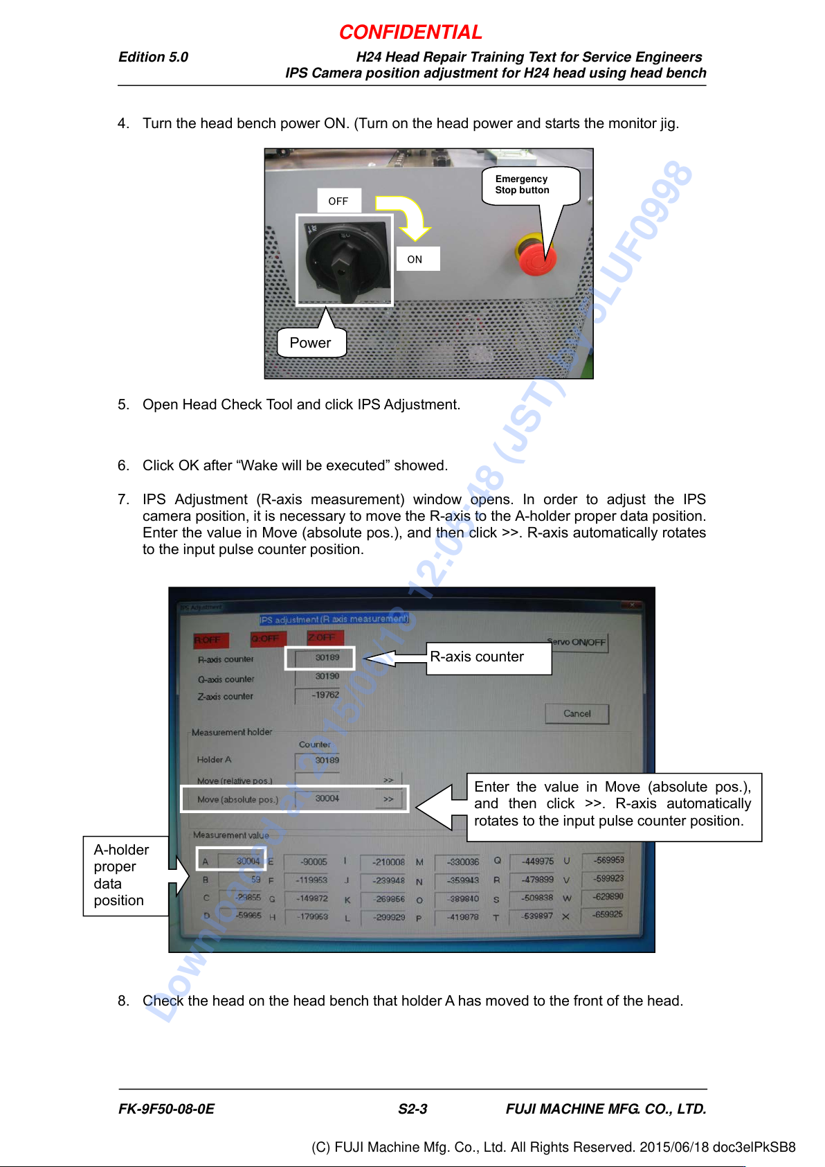
4. Turn the head bench power ON. (Turn on the head power and starts the monitor jig.
5. Open Head Check Tool and click IPS Adjustment.
6. Click OK after “Wake will be executed” showed.
7. IPS Adjustment (R-axis measurement) window opens. In order to adjust the IPS
camera position, it is necessary to move the R-axis to the A-holder proper data position.
Enter the value in Move (absolute pos.), and then click >>. R-axis automatically rotates
to the input pulse counter position.
8. Check the head on the head bench that holder A has moved to the front of the head.
A-holder
proper
data
position
Enter the value in Move (absolute pos.),
and then click >>. R-axis automatically
rotates to the input pulse counter position.
R-axis counter
OFF
Emergency
Stop button
ON
Power
FK-9F50-08-0E S2-3 FUJI MACHINE MFG. CO., LTD.
CONFIDENTIAL
Downloaded at 2015/06/18 12:05:48 (JST) by 5LUF0998
(C) FUJI Machine Mfg. Co., Ltd. All Rights Reserved. 2015/06/18 doc3elPkSB8