1_H24维修手册.pdf - 第185页
E d i ti o n 5 .0 H 24 H ead R ep ai r T r ai n i n g T ext f o r S er vi ce E n g i n ee r s Pr o p e r d at a m e a s u r e m e n t fo r H 2 4 h e a d u s i n g h e a d b e n c h 16. C l i c k [ O K ] . N ex t , m e as…
Edition 5.0 H24 Head Repair Training Text for Service Engineers
Proper data measurement for H24 head using head bench
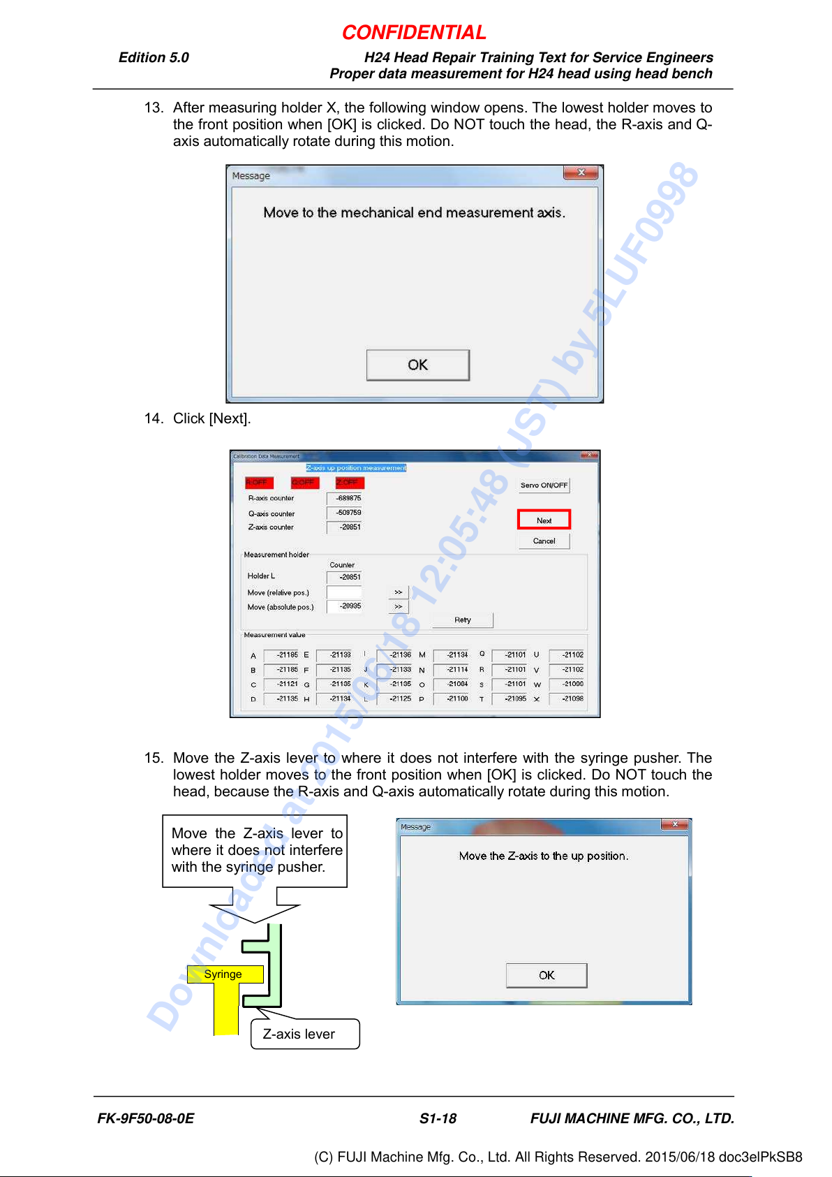
13. After measuring holder X, the following window opens. The lowest holder moves to
the front position when [OK] is clicked. Do NOT touch the head, the R-axis and Q-
axis automatically rotate during this motion.
14. Click [Next].
15. Move the Z-axis lever to where it does not interfere with the syringe pusher. The
lowest holder moves to the front position when [OK] is clicked. Do NOT touch the
head, because the R-axis and Q-axis automatically rotate during this motion.
Move the Z-axis lever to
where it does not interfere
with the syringe pusher.
Z-axis lever
Syringe
FK-9F50-08-0E S1-18 FUJI MACHINE MFG. CO., LTD.
CONFIDENTIAL
Downloaded at 2015/06/18 12:05:48 (JST) by 5LUF0998
(C) FUJI Machine Mfg. Co., Ltd. All Rights Reserved. 2015/06/18 doc3elPkSB8
Edition 5.0 H24 Head Repair Training Text for Service Engineers
Proper data measurement for H24 head using head bench
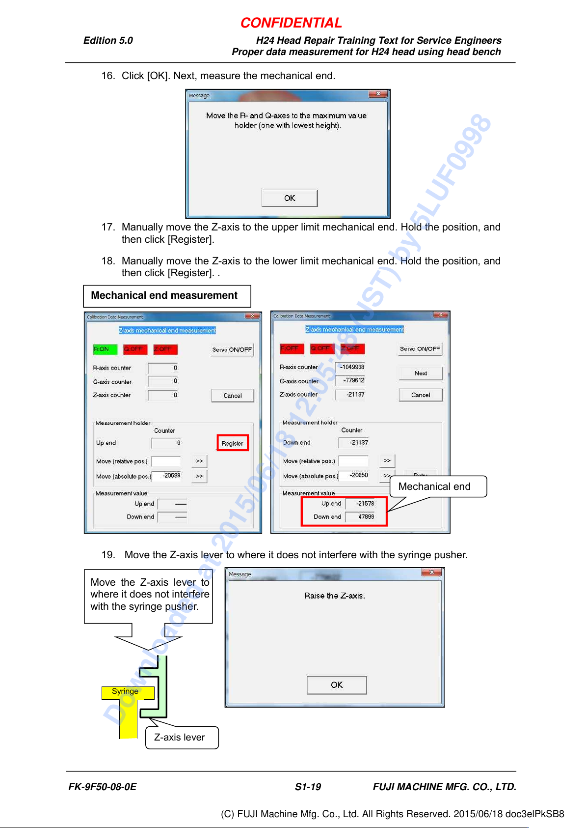
16. Click [OK]. Next, measure the mechanical end.
17. Manually move the Z-axis to the upper limit mechanical end. Hold the position, and
then click [Register].
18. Manually move the Z-axis to the lower limit mechanical end. Hold the position, and
then click [Register]. .
19. Move the Z-axis lever to where it does not interfere with the syringe pusher.
Mechanical end measurement
Move the Z-axis lever to
where it does not interfere
with the syringe pusher.
Z-axis lever
Syringe
Mechanical end
FK-9F50-08-0E S1-19 FUJI MACHINE MFG. CO., LTD.
CONFIDENTIAL
Downloaded at 2015/06/18 12:05:48 (JST) by 5LUF0998
(C) FUJI Machine Mfg. Co., Ltd. All Rights Reserved. 2015/06/18 doc3elPkSB8
Edition 5.0 H24 Head Repair Training Text for Service Engineers
Proper data measurement for H24 head using head bench
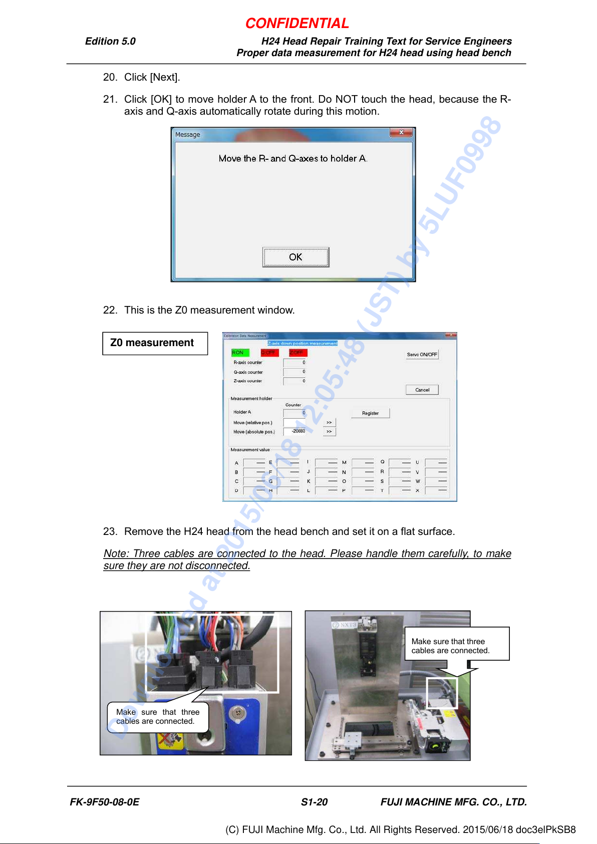
20. Click [Next].
21. Click [OK] to move holder A to the front. Do NOT touch the head, because the R-
axis and Q-axis automatically rotate during this motion.
22. This is the Z0 measurement window.
23. Remove the H24 head from the head bench and set it on a flat surface.
Note: Three cables are connected to the head. Please handle them carefully, to make
sure they are not disconnected.
Z0 measurement
Make sure that three
cables are connected.
Make sure that three
cables are connected.
FK-9F50-08-0E S1-20 FUJI MACHINE MFG. CO., LTD.
CONFIDENTIAL
Downloaded at 2015/06/18 12:05:48 (JST) by 5LUF0998
(C) FUJI Machine Mfg. Co., Ltd. All Rights Reserved. 2015/06/18 doc3elPkSB8