1_H24维修手册.pdf - 第83页
E d i ti o n 5 .0 H 24 H ead R ep ai r T r ai n i n g T e xt f o r S er v i ce E n g i n eer s R e p l a c i n g a n d A d j u s ti n g th e S te p p i n g M o to r Ch ap t er 7 - R e pl a c i ng a nd A d j u s ti n g th…

CONFIDENTIAL
Downloaded at 2015/06/18 12:05:48 (JST) by 5LUF0998
(C) FUJI Machine Mfg. Co., Ltd. All Rights Reserved. 2015/06/18 doc3elPkSB8
Edition 5.0 H24 Head Repair Training Text for Service Engineers
Replacing and Adjusting the Stepping Motor
Chapter 7 - Replacing and Adjusting the Stepping Motor
7.1 Setting Up the Head I/O Check Jig
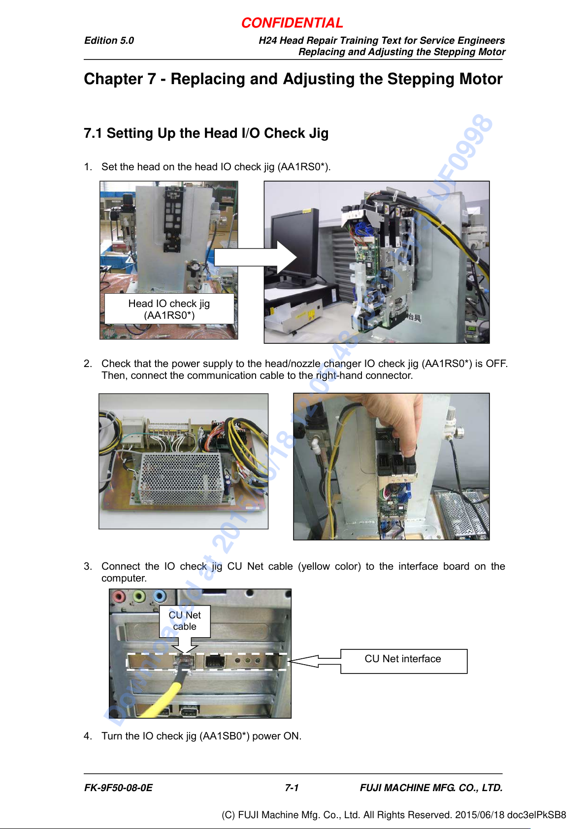
1. Set the head on the head IO check jig (AA1RS0*).
2. Check that the power supply to the head/nozzle changer IO check jig (AA1RS0*) i s OF F.
Then, connect the communication cable to the right-hand connector.
3. Connect the IO check jig CU Net cable (yellow color) to the interface board on the
computer.
4. Turn the IO check jig (AA1SB0*) power ON.
CU Net
cable
CU Net interface
Head IO check jig
(AA1RS0*)
FK-9F50-08-0E 7-1 FUJI MACHINE MFG. CO., LTD.
CONFIDENTIAL
Downloaded at 2015/06/18 12:05:48 (JST) by 5LUF0998
(C) FUJI Machine Mfg. Co., Ltd. All Rights Reserved. 2015/06/18 doc3elPkSB8
Edition 5.0 H24 Head Repair Training Text for Service Engineers
Replacing and Adjusting the Stepping Motor
7.2 Removing the Stepping Motor
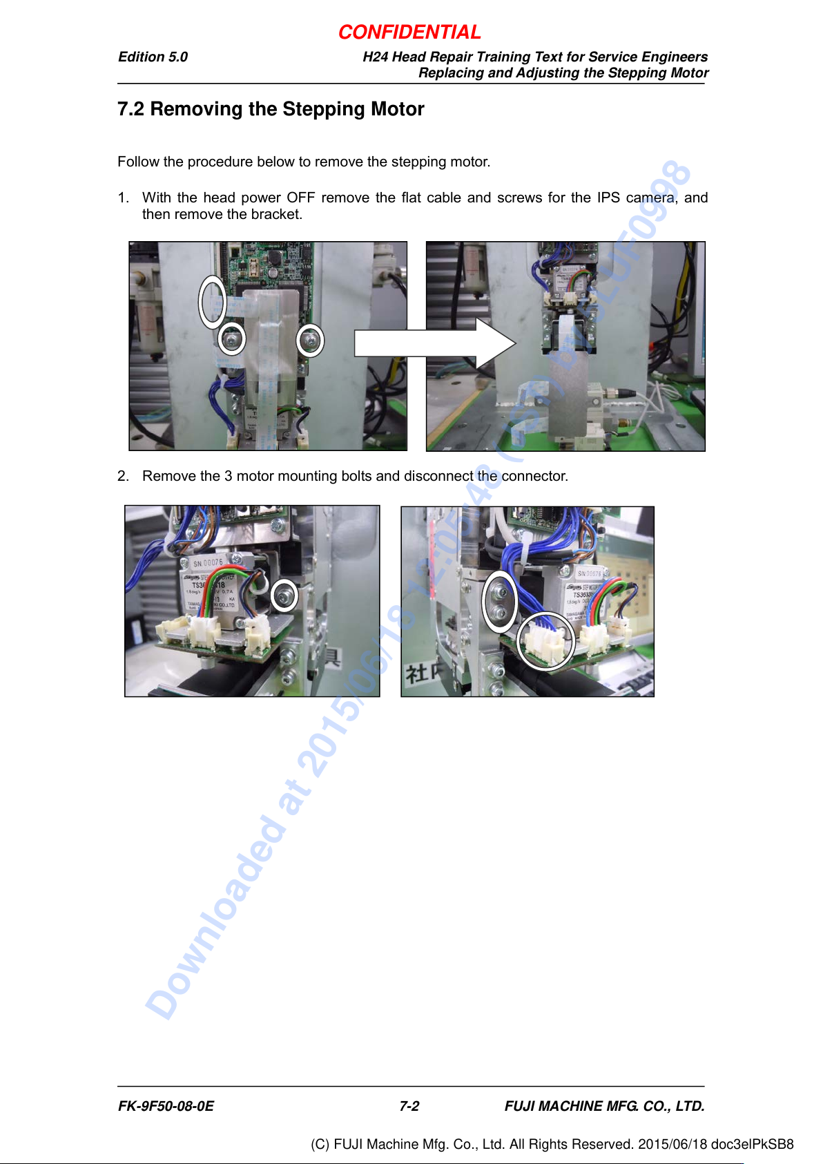
Follow the procedure below to remove the stepping motor.
1. With the head power OFF remove the flat cable and screws for the IPS camera, and
then remove the bracket.
2. Remove the 3 motor mounting bolts and disconnect the connector.
FK-9F50-08-0E 7-2 FUJI MACHINE MFG. CO., LTD.
CONFIDENTIAL
Downloaded at 2015/06/18 12:05:48 (JST) by 5LUF0998
(C) FUJI Machine Mfg. Co., Ltd. All Rights Reserved. 2015/06/18 doc3elPkSB8