00197394-03_AI_Smart-Pin-Support_X-S_DE_EN.pdf - 第101页
3 Installation 3.2 Installation of Pin PIcker Assembly Instructions / Montageanleitung SIPLACE X-Series S Smart Pin Support 05/2019 101 Running the round cable ► Running the round cable as shown in the diagrams: Fig.24:…
3 Installation
3.2 Installation of Pin PIcker
100 Assembly Instructions / Montageanleitung SIPLACE X-Series S Smart Pin Support 05/2019
3.2.3 Establishing Electrical Connections
You need the following parts for each pin picker:
●
5x cable ties W=2.4mm L=92mm TYB-23M "black" [00805140-xx]
●
1x mounting base MB1 [00362777-xx]
●
1x DIN7991-M3x6-A2 screw [03016240-xx]
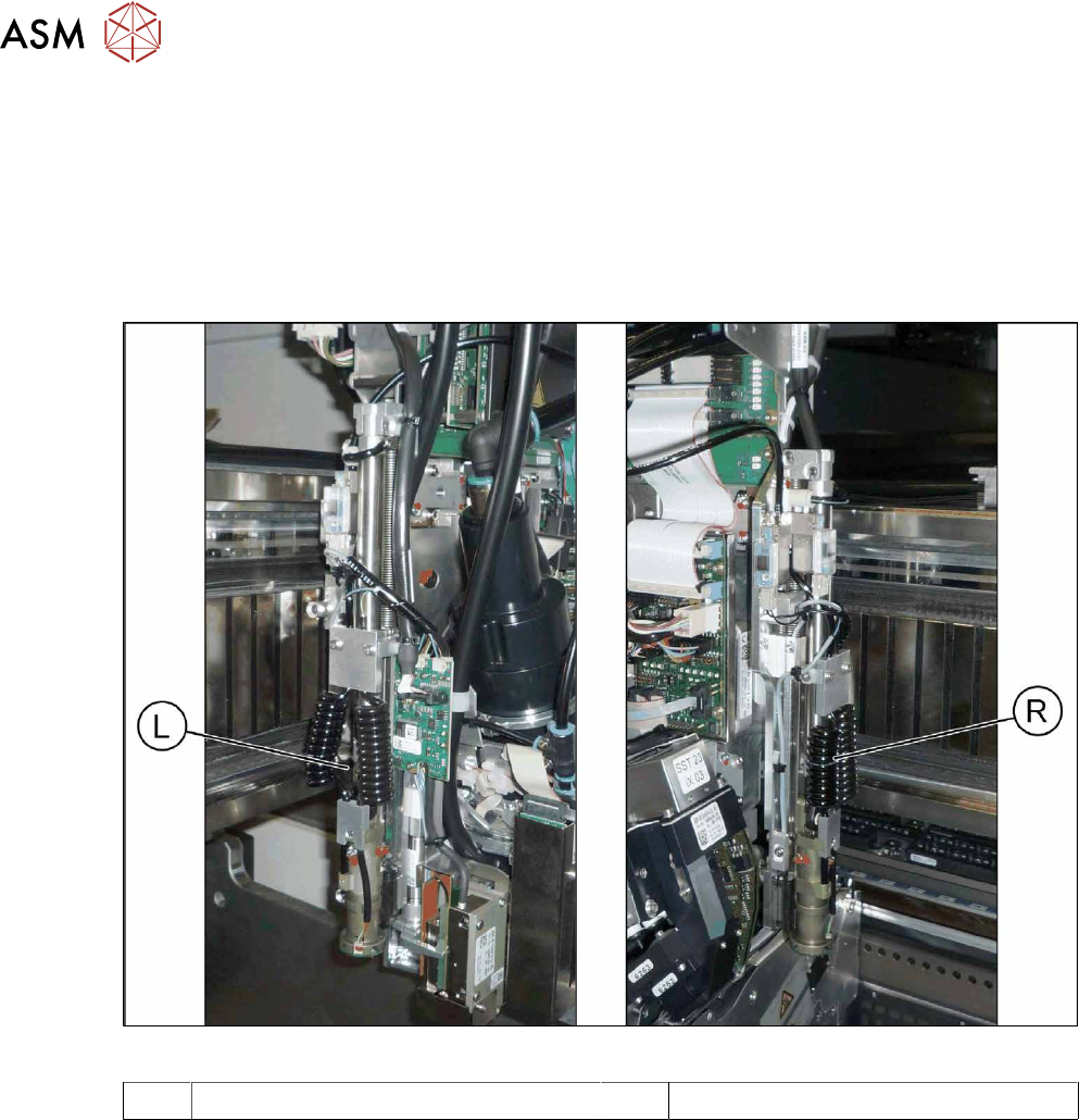
Overview
Fig.23: Pin picker left and right
L Pin picker left R Pin picker right
3 Installation
3.2 Installation of Pin PIcker
Assembly Instructions / Montageanleitung SIPLACE X-Series S Smart Pin Support 05/2019 101
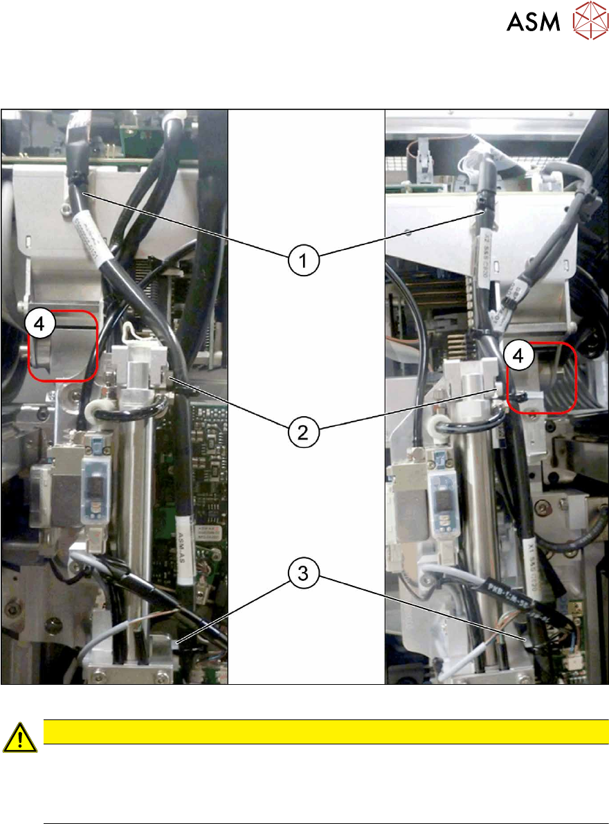
Running the round cable
► Running the round cable as shown in the diagrams:
Fig.24: Overview of cables - left and right
CAUTION
Cable and hose path
► Make sure that the entry areas for the gantry buffer (4) are kept free of cables and
hoses. These could be trapped otherwise.
► Observe the detail views in the following diagram.
► Fasten the round cable with a cable tie at(1). If there is no suitable lug here, attach an adhes-
ive pedestal.
► Screw a mounting pedestal into place at (2). Fix the round cable to the mounting pedestal with
a cable tie.
► Screw a mounting pedestal into place at (3). Fix the round cable to the mounting pedestal with
a cable tie.
3 Installation
3.2 Installation of Pin PIcker
102 Assembly Instructions / Montageanleitung SIPLACE X-Series S Smart Pin Support 05/2019
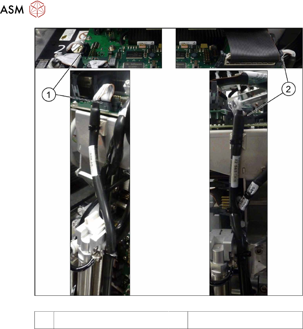
Fig.25: Connection on the head interface
1 Connection to the board "head interface
C700-L" (left) to connector X11
2 Connection to the board "head interface
C700-R" (right) to connector X13
► Connect the round cable to the head interface.