00197394-03_AI_Smart-Pin-Support_X-S_DE_EN.pdf - 第99页
3 Installation 3.2 Installation of Pin PIcker Assembly Instructions / Montageanleitung SIPLACE X-Series S Smart Pin Support 05/2019 99 3.2.2 Fitting the Spacers Overview Fig.20: Spacer Spacer (buffer) for SPS [03094012-…
3 Installation
3.2 Installation of Pin PIcker
98 Assembly Instructions / Montageanleitung SIPLACE X-Series S Smart Pin Support 05/2019
3.2 Installation of Pin PIcker
3.2.1 Mechanical Installation of Pin Picker
NOTICE
Installation on left/right side
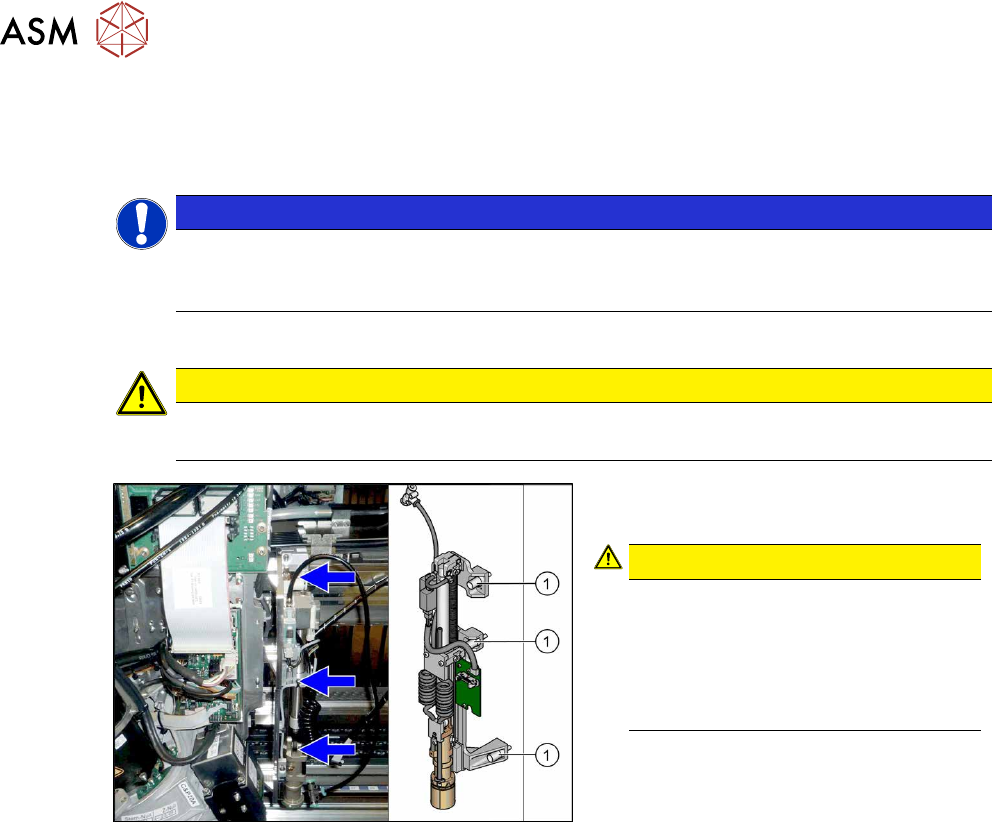
The installation procedure is shown using the example of the right-hand side. Any differ-
ences will be explicitly indicated.
► If not prefitted: connect the pneumatic hose supplied to the pin picker.
CAUTION
Pneumatic hose
It is difficult to connect the pneumatic hose when already installed.
Fig.19: Screwing the pin picker into place
► Use three screws(1) (captive) to fix the
pin picker to the head mount.
CAUTION!
Tighten the screws to a torque of 2.7 N.
Secure the screws with locking varnish
(Loctite243).
Check the cables nearby, to ensure
that the return spring does not rub
against them and damage them.
.
3 Installation
3.2 Installation of Pin PIcker
Assembly Instructions / Montageanleitung SIPLACE X-Series S Smart Pin Support 05/2019 99
3.2.2 Fitting the Spacers
Overview
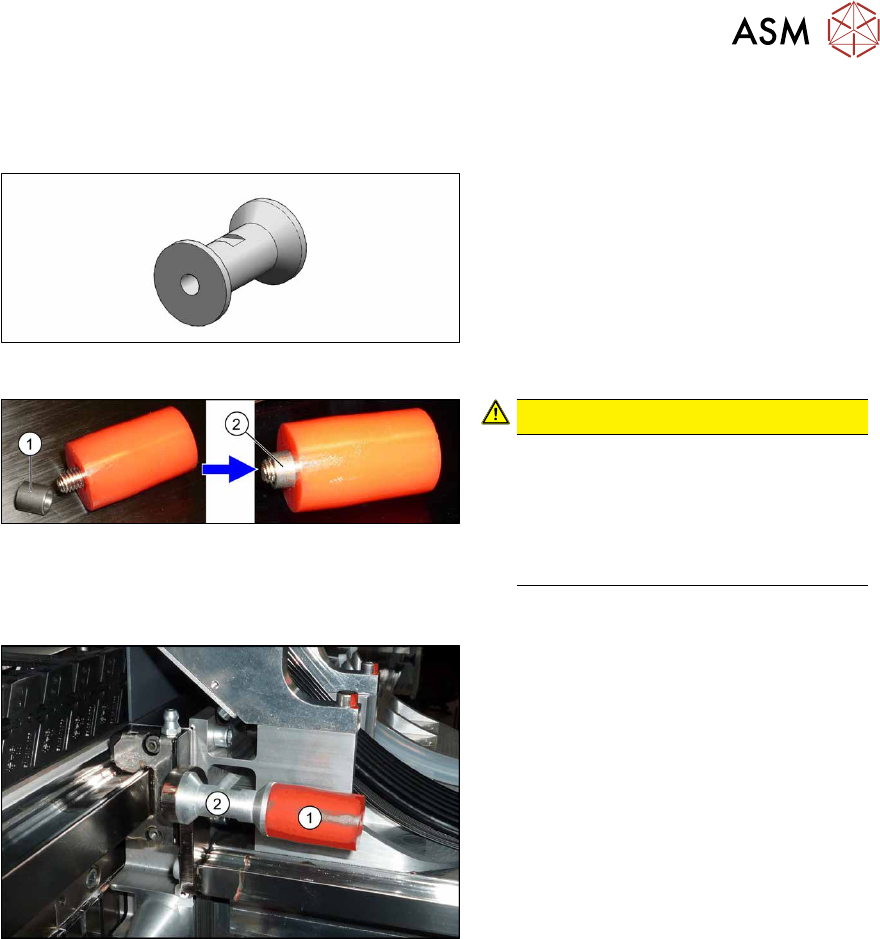
Fig.20: Spacer
Spacer (buffer) for SPS [03094012-xx]
The spacers are needed if the pin picker is
fitted towards the gantry root at gantry 1 or
3. This is always the case, except at gantry
3 in X3 S machines. (See also 2.4 "Possible
Configurations/Required Equipment" [}82] )
Fig.21: Bushing in buffer
CAUTION!
The bushing (1) can easily fall out of
the buffers.
Make sure that you do not lose these.
Make sure that the bushing is in the
buffer before you screw the buffer into
place (2).
.
Installation
Fig.22: Buffer with spacer
► Remove the screw fastening the buf-
fer(1) and then remove the buffer.
Make sure that you do not lose the
bushing.
► Screw the spacer(2) into place.
► Screw the buffer onto the spacer. Make
sure that you do not lose the bushing.
► Repeat this procedure for the second buffer on the gantry root.
► Carefully push the head mount against the buffer and check whether cables have been
trapped. Correct how the cables are run, if this occurs.
► Repeat this procedure for all gantries affected.
3 Installation
3.2 Installation of Pin PIcker
100 Assembly Instructions / Montageanleitung SIPLACE X-Series S Smart Pin Support 05/2019
3.2.3 Establishing Electrical Connections
You need the following parts for each pin picker:
●
5x cable ties W=2.4mm L=92mm TYB-23M "black" [00805140-xx]
●
1x mounting base MB1 [00362777-xx]
●
1x DIN7991-M3x6-A2 screw [03016240-xx]
Overview
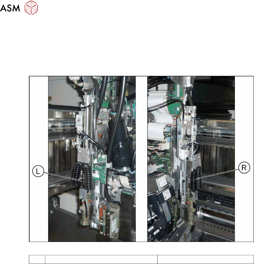
Fig.23: Pin picker left and right
L Pin picker left R Pin picker right