00197394-03_AI_Smart-Pin-Support_X-S_DE_EN.pdf - 第109页
3 Installation 3.4 Installing the W5 magazine (SIPLACE X4i S) Assembly Instructions / Montageanleitung SIPLACE X-Series S Smart Pin Support 05/2019 109 3.4.4 Connecting the "Magazine Recognition" Board (If Pres…
3 Installation
3.4 Installing the W5 magazine (SIPLACE X4i S)
108 Assembly Instructions / Montageanleitung SIPLACE X-Series S Smart Pin Support 05/2019
3.4.3 Checking/Correcting the Vertical Distance
If you have not already done so, you need to check the height of the second NC row.
► For better access when measuring on the outer side, push the placement head inwards.
► Move the gantry so that the placement head is roughly on the planned NC position.
NOTICE
Avoid scratching the magnetic strip.
Make sure that the tip of the measuring scale does not touch the magnetic strip, as this
might scratch it!
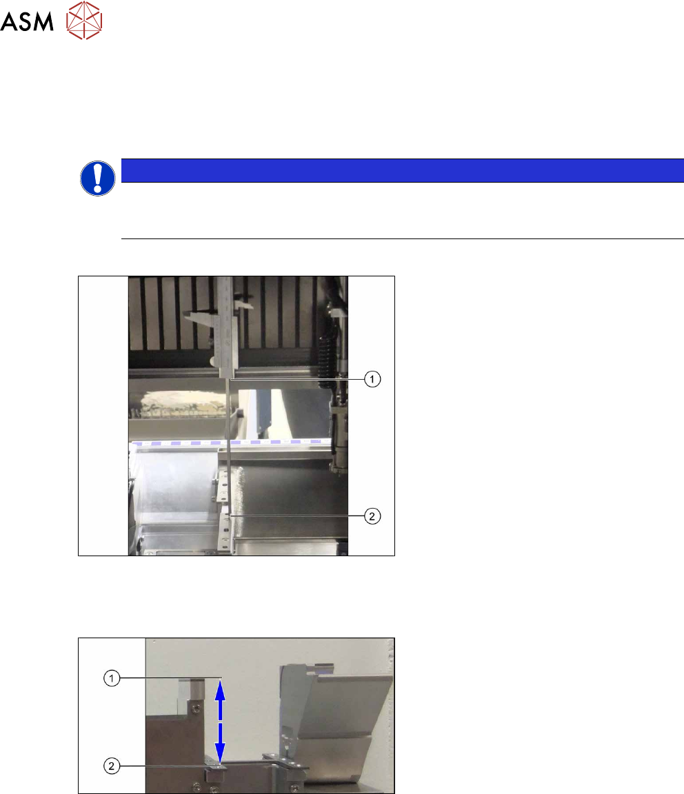
Checking the height of the second NC row
Fig.35: Height check (using the example of the holder for
second NC row)
► Check the height of the installed sup-
ports or holders for the second NC row.
► Position the measuring scale vertically
onto the top edge of the X axis lower
linear guide at (1) and measure the dis-
tance to the support or holder contact
surface (2).
Measured value: 150.0mm +/‑0.2mm
► If the distance is smaller, you will need
to remove the shim plates from under
the contact surfaces and repeat the
measurement.
Checking the height of the ASP support
Fig.36: Checking the height of the ASP support (using
example of X3 S/X4 S representing the measuring principle)
If the height of the second NC row is cor-
rectly set to 150.0mm +/- 0.2 mm, you will
need to check the distance between the NC
and the ASP support.
► Position the measuring scale vertically
onto the contact surface of the NC (1)
and measure down to the ASP support
(2).
Measured value: 77mm +/‑0.2mm
► If the distance is outside the tolerance
range, insert or remove shim plates as
required.
3 Installation
3.4 Installing the W5 magazine (SIPLACE X4i S)
Assembly Instructions / Montageanleitung SIPLACE X-Series S Smart Pin Support 05/2019 109
3.4.4 Connecting the "Magazine Recognition" Board (If Present)
NOTICE
From SW 706.1 SP2
► Configuration of the magazines is performed automatically in machines before SW
706.1 SP2, using the "magazine recognition" board.
► If older machines with SPS are upgraded to a version equal to or higher than SW
706.1 SP2, the existing magazine configuration is kept in the software. If additional
magazines without board are fitted into these upgraded machines, these must be
manually configured via the software (Autoconfig).
► From SW 706.1 SP2, magazines can be fitted without the "magazine recognition"
function. In this case, the machine can only be configured manually via the software
(Autoconfig).
Proceed with chapter 3.3.4 "Assembling the W5 magazine" [}106] if this applies.
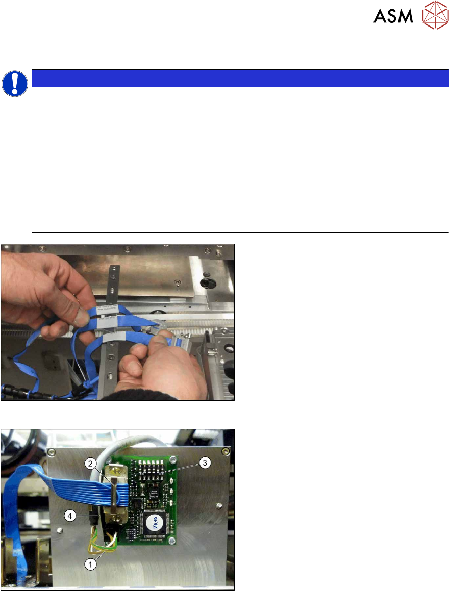
Fig.37: Data cable for NC 2 and SPS
► Locate the required cables.
Four labeled data cables have been pre-
pared in the machine for the various config-
urations of NCs with and without Smart Pin
Support (SPS).
●
X1*a (NC 1)
●
x1*b (SPS (1) or NC 2 (without SPS))
●
X1*c (NC 2 with SPS)
●
X1*d (SPS2)
Fig.38: Board connection (using example of Q10)
► If not fitted, screw the board to the un-
derside of the magazine with four
M2.5x4 screws. The connection for the
flat ribbon cable should point towards
the angular metal bracket(4).
► Connect the power supply cable (1) to
connector X8 on the magazine board.
► Fit the strain relief for the voltage sup-
ply cable to the metal bracket and then
fix the cable into place.
► Connect the "NC SPS ribbon cable" (2)
to connector X6 on the board and
screw into place.
► Set the jumper (3) on the DIP
switchS1. (see below )
3 Installation
3.4 Installing the W5 magazine (SIPLACE X4i S)
110 Assembly Instructions / Montageanleitung SIPLACE X-Series S Smart Pin Support 05/2019
3.4.4.1 DIP Switch S1 - Jumper Assignment
S1.1 S1.2 Magazine connected at
ON OFF NC connection 2
OFF ON NC connection 4
S1.4 S1.5 S1.6 Meaning
OFF OFF OFF Garage is switched off
ON OFF OFF Garage type W5
X X ON Reserved
NOTICE
Jumper S1.3
Jumper S1.3 is not used.
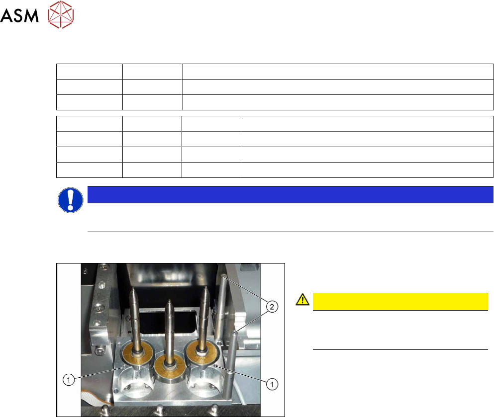
3.4.5 Assembling the W5 magazine
Fig.39: W5 magazine (using example of X4 S)
► Fix the magazine into place with the
four fastening screws(1).
CAUTION!
Observe the installation position.
The calibration fiducials (2) need to be
on the right-hand side.
.