00197394-03_AI_Smart-Pin-Support_X-S_DE_EN.pdf - 第112页
3 Installation 3.5 Installing the Q10 Magazine 112 Assembly Instructions / Montageanleitung SIPLACE X-Series S Smart Pin Support 05/2019 Spacer plates Fig.41: Spacer plate labeling IC and FC are marked on the top and bo…
3 Installation
3.5 Installing the Q10 Magazine
Assembly Instructions / Montageanleitung SIPLACE X-Series S Smart Pin Support 05/2019 111
3.5 Installing the Q10 Magazine
The Q10 magazine is fitted in place of a FC camera or a coplanarity module..
See also
2 2.4 "Possible Configurations/Required Equipment" [}82]
3.5.1 Installing the Q10 Magazine Holder
WARNING
Incorrectly labeled spacers for stationary cameras
During retrofitting or conversion of stationary cameras or ("Smart Pin Support) Q10"
magazines, pay attention to correct fitting of the spacers.
► Also read the technical information [DE:TI2014‑02D04] [EN:TI2014-02E04].
► Incorrect installation creates a risk of a crash occurring!
The holder is fixed on two spacer plates, which have already been screwed to the screw fixing
points on the machine base.
The procedure for fitting these spacer plates and for fixing the mount is in principle the same at all
locations. Any differences are indicated in the following section.
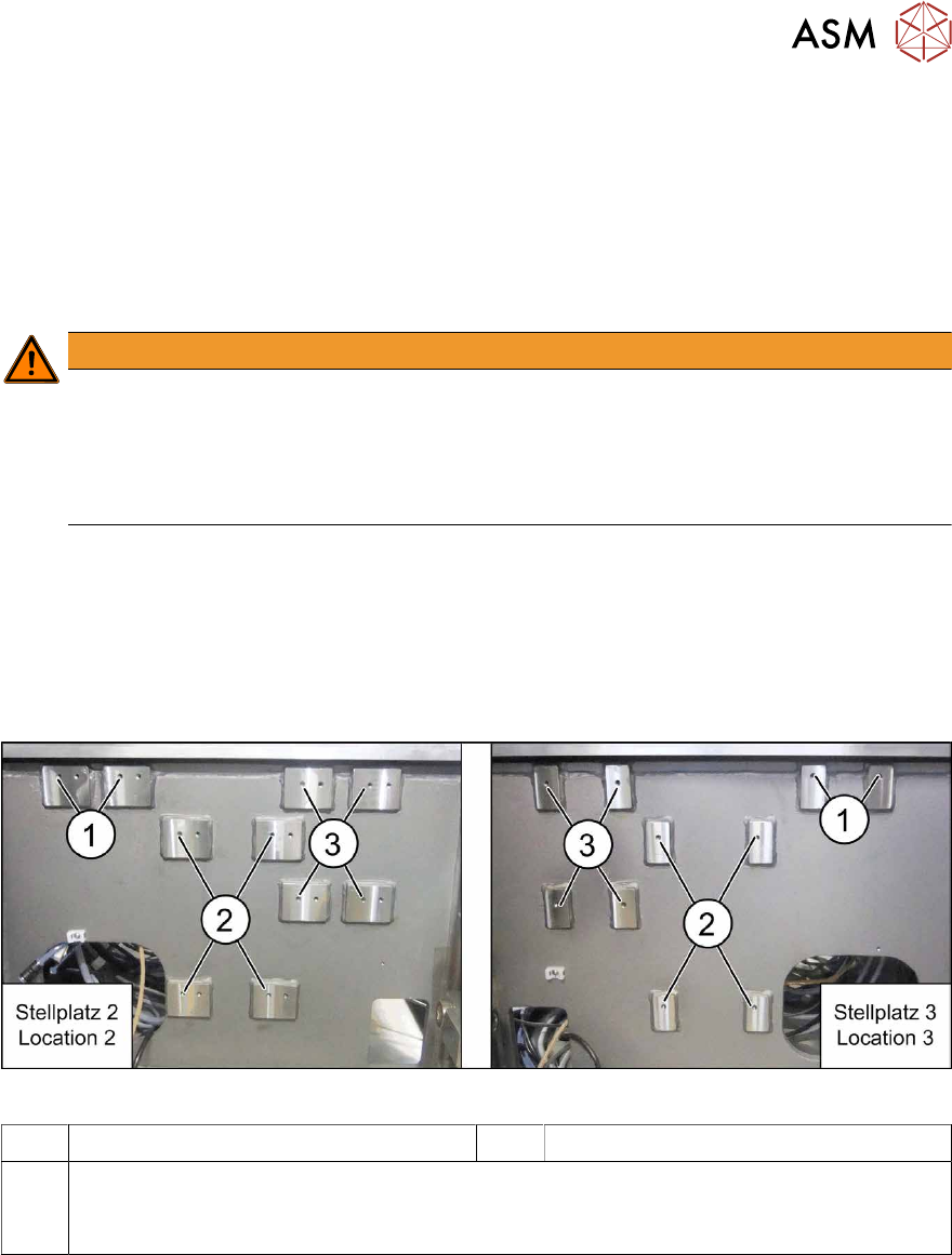
Screw fixing points at location 2 and 3
The spacer plates are fixed to the relevant screw fixing points in the machine base.
Fig.40: Screw points at location 2 (left) and 3 (right)
1 Screw fixing points for the reject bin 2 Screw points for the IC camera type 33
3 Screw points for the Q10 magazine mount (otherwise: FC camera type 25)
The screw points at location 2 and 3 are mirrored.
Use the left holes at location 2.
3 Installation
3.5 Installing the Q10 Magazine
112 Assembly Instructions / Montageanleitung SIPLACE X-Series S Smart Pin Support 05/2019
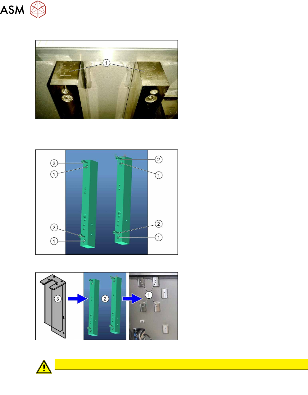
Spacer plates
Fig.41: Spacer plate labeling
IC and FC are marked on the top and bot-
tom of the spacer plates.
When fitting the Q10 magazine mount, the
FC mark must point upwards (1).
Fitting the spacer plates
Fig.42: Spacer plates
1. Fastening screws for fixing the spacer
plates to the machine base
(screws: M6x45 [03042579-xx])
2. Screw points for the Q10 magazine
mount
(screws: M6x25 [03042575-xx])
Fig.43: Fitting the Q10 magazine
► Use four fastening screws to fix the
spacer plates(2) to the machine
base(1).
► Use four fastening screws to fit the Q10
magazine mount(3) to the spacer
plates(1).
CAUTION
Observe the installation height
When fitting the mount, observe the correct installation height. Otherwise there is the
danger of a crash!
3 Installation
3.5 Installing the Q10 Magazine
Assembly Instructions / Montageanleitung SIPLACE X-Series S Smart Pin Support 05/2019 113
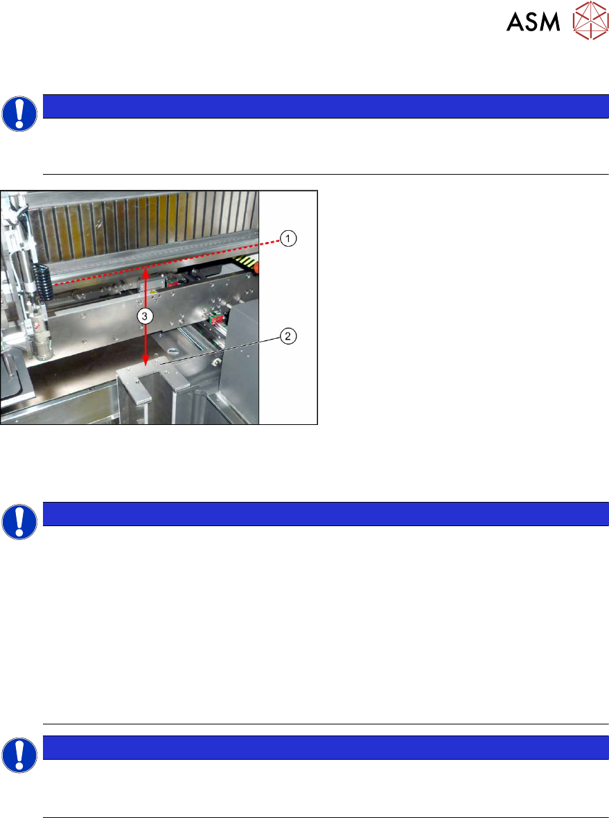
3.5.2 Checking/Correcting the Vertical Distance
NOTICE
Avoid scratching the magnetic strip.
Make sure that the tip of the measuring scale does not touch the magnetic strip, as this
might scratch it!
Fig.44: Checking the Height
► For measurement, push the gantry over
the magazine holder.
► Position the measuring scale vertically
onto the top edge (1)of the X axis lower
linear guide and measure the distance
to the support surface (2).
Measured value(3): 227.0mm +/‑0.2mm
► If the distance is outside the tolerance
range, insert or remove shim plates as
required.
3.5.3 Connecting the "Magazine Recognition" Board (If Present)
NOTICE
From SW 706.1 SP2
► Configuration of the magazines is performed automatically in machines before SW
706.1 SP2, using the "magazine recognition" board.
► If older machines with SPS are upgraded to a version equal to or higher than SW
706.1 SP2, the existing magazine configuration is kept in the software. If additional
magazines without board are fitted into these upgraded machines, these must be
manually configured via the software (Autoconfig).
► From SW 706.1 SP2, magazines can be fitted without the "magazine recognition"
function. In this case, the machine can only be configured manually via the software
(Autoconfig).
Proceed with chapter 3.3.4 "Assembling the W5 magazine" [}106] if this applies.
NOTICE
Configuring the Q 10 magazine
► If the Q10 magazine is fitted together with an MTC at location 2, the configuration is
always performed manually via the software.