00197394-03_AI_Smart-Pin-Support_X-S_DE_EN.pdf - 第111页
3 Installation 3.5 Installing the Q10 Magazine Assembly Instructions / Montageanleitung SIPLACE X-Series S Smart Pin Support 05/2019 111 3.5 Installing the Q10 Magazine The Q10 magazine is fitted in place of a FC camera …
3 Installation
3.4 Installing the W5 magazine (SIPLACE X4i S)
110 Assembly Instructions / Montageanleitung SIPLACE X-Series S Smart Pin Support 05/2019
3.4.4.1 DIP Switch S1 - Jumper Assignment
S1.1 S1.2 Magazine connected at
ON OFF NC connection 2
OFF ON NC connection 4
S1.4 S1.5 S1.6 Meaning
OFF OFF OFF Garage is switched off
ON OFF OFF Garage type W5
X X ON Reserved
NOTICE
Jumper S1.3
Jumper S1.3 is not used.
3.4.5 Assembling the W5 magazine
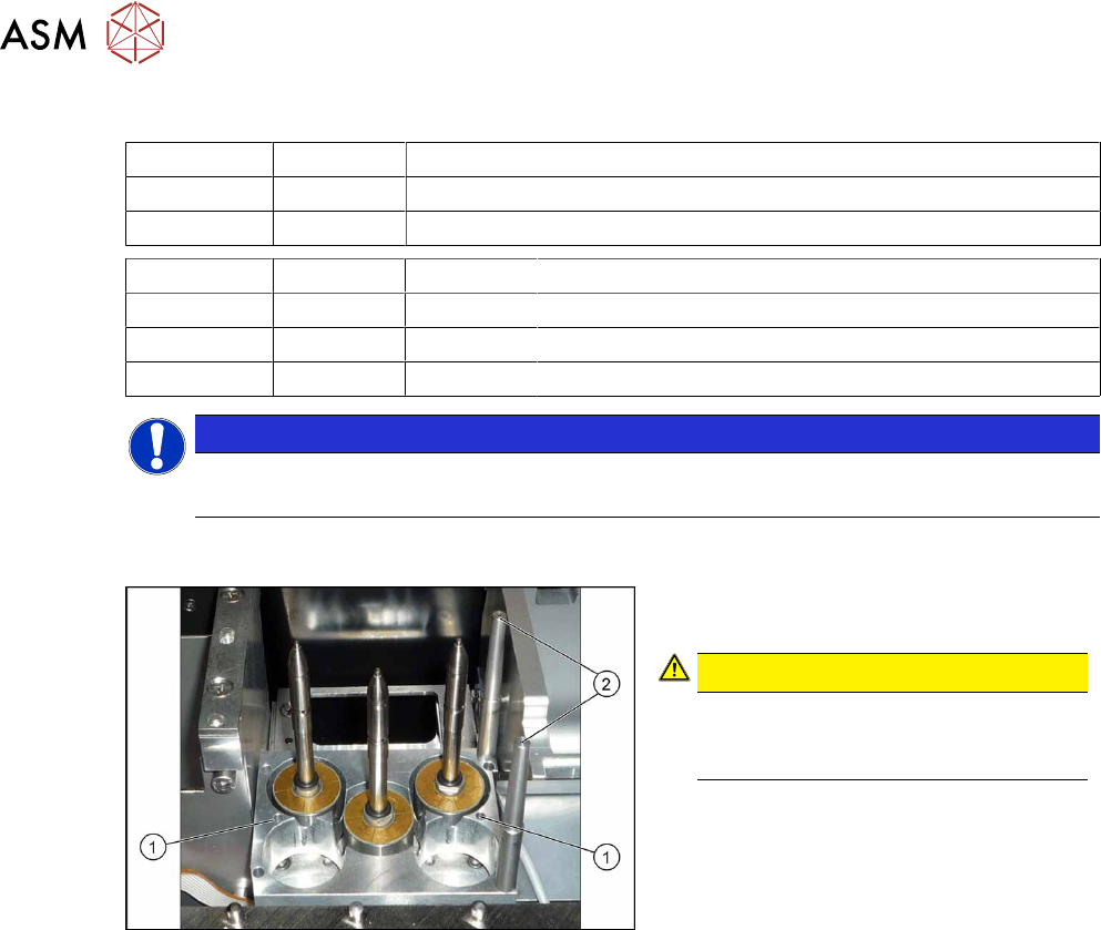
Fig.39: W5 magazine (using example of X4 S)
► Fix the magazine into place with the
four fastening screws(1).
CAUTION!
Observe the installation position.
The calibration fiducials (2) need to be
on the right-hand side.
.
3 Installation
3.5 Installing the Q10 Magazine
Assembly Instructions / Montageanleitung SIPLACE X-Series S Smart Pin Support 05/2019 111
3.5 Installing the Q10 Magazine
The Q10 magazine is fitted in place of a FC camera or a coplanarity module..
See also
2 2.4 "Possible Configurations/Required Equipment" [}82]
3.5.1 Installing the Q10 Magazine Holder
WARNING
Incorrectly labeled spacers for stationary cameras
During retrofitting or conversion of stationary cameras or ("Smart Pin Support) Q10"
magazines, pay attention to correct fitting of the spacers.
► Also read the technical information [DE:TI2014‑02D04] [EN:TI2014-02E04].
► Incorrect installation creates a risk of a crash occurring!
The holder is fixed on two spacer plates, which have already been screwed to the screw fixing
points on the machine base.
The procedure for fitting these spacer plates and for fixing the mount is in principle the same at all
locations. Any differences are indicated in the following section.
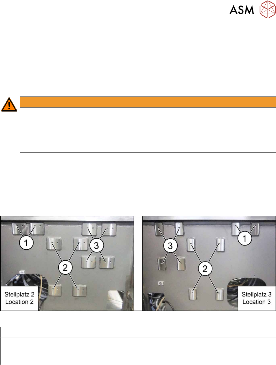
Screw fixing points at location 2 and 3
The spacer plates are fixed to the relevant screw fixing points in the machine base.
Fig.40: Screw points at location 2 (left) and 3 (right)
1 Screw fixing points for the reject bin 2 Screw points for the IC camera type 33
3 Screw points for the Q10 magazine mount (otherwise: FC camera type 25)
The screw points at location 2 and 3 are mirrored.
Use the left holes at location 2.
3 Installation
3.5 Installing the Q10 Magazine
112 Assembly Instructions / Montageanleitung SIPLACE X-Series S Smart Pin Support 05/2019
Spacer plates
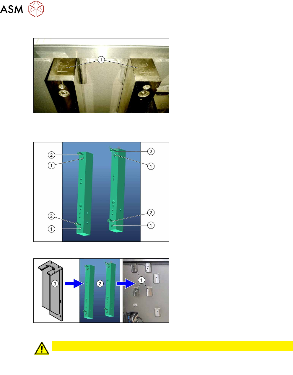
Fig.41: Spacer plate labeling
IC and FC are marked on the top and bot-
tom of the spacer plates.
When fitting the Q10 magazine mount, the
FC mark must point upwards (1).
Fitting the spacer plates
Fig.42: Spacer plates
1. Fastening screws for fixing the spacer
plates to the machine base
(screws: M6x45 [03042579-xx])
2. Screw points for the Q10 magazine
mount
(screws: M6x25 [03042575-xx])
Fig.43: Fitting the Q10 magazine
► Use four fastening screws to fix the
spacer plates(2) to the machine
base(1).
► Use four fastening screws to fit the Q10
magazine mount(3) to the spacer
plates(1).
CAUTION
Observe the installation height
When fitting the mount, observe the correct installation height. Otherwise there is the
danger of a crash!