00197394-03_AI_Smart-Pin-Support_X-S_DE_EN.pdf - 第81页
2 Brief Description 2.1 Product Description Assembly Instructions / Montageanleitung SIPLACE X-Series S Smart Pin Support 05/2019 81 2 Brief Description Smart Pin Support facilitates automatic positioning of pins on the …

1 Introduction
1.5 Abbreviations
80 Assembly Instructions / Montageanleitung SIPLACE X-Series S Smart Pin Support 05/2019
1.5 Abbreviations
Abbreviations Description
PA, PA1, PA2 Placement area, Placement area 1, Placement area 2
CO Component
C&P Collect&Place
CPP Collect&Pick&Place head
ESD Electrostatic sensitive device
EMC Electromagnetic compatibility
PCB PCB board
P&P Pick&Place
NC Nozzle changers
TH TwinHead

2 Brief Description
2.1 Product Description
Assembly Instructions / Montageanleitung SIPLACE X-Series S Smart Pin Support 05/2019 81
2 Brief Description
Smart Pin Support facilitates automatic positioning of pins on the lifting table plate with the help of
the programming system. The pins can therefore be automatically positioned by the machine while
a new job is being downloaded to the machine.
2.1 Product Description
The "Smart Pin Support" option is available for the X3 S, X4 S and X4i S machines.
The pins are positioned on the lifting table plate with the help of SIPLACE Pro. The position of
these pins is described in SIPLACE Pro in the same way as in a placement list. The information is
then sent to the machine, together with the setup. The machine recognizes the available pins and
sets these at the programmed positions.
The pins are positioned with the help of the pin pickers. These are located on the gantries.
There are two magazine types available for this, W5 and Q10, which are recognized by the soft-
ware.
2.2 Prerequisites
The following conditions must be fulfilled for installation of the Smart Pin Support:
●
Station SW >706.1 SP1
●
SIPLACE Pro >10.1 SP1
2.3 Restrictions
●
You always need to install a pin picker at each of the machine gantries. These are fixed to the
left or right side of the gantry, depending on the configuration.
The X3 S machine, for example, only has a pin picker fitted on the right of gantry 3. This
means that the pins can only reach a range of 280 mm, not the entire placement area.
●
The W5 and Q10 magazine can be fitted.
NOTICE
From SW 706.1 SP2
From SW 706.1 SP2, magazines can be fitted without the "magazine recognition" function.
In this case, the machine can only be configured manually via the software (Autoconfig).
●
For all valid configurations, refer to section 2.4 "Possible Configurations/Required Equip-
ment" [}82].
●
Due to the pin picker, tracks 38 to 40 can not be reached by the placement head at locations
1 and 3. For this reason, the dummy feeder is used (see 3.7 "Inserting the dummy
feeder" [}115]).
●
The placement area is restricted in the X direction. The extent of this restriction depends on
the specific configuration.
Example:
SIPLACE X4S (PA1 with C&P20P / C&P20P, PA2 with Twin / CPP)
Restriction at gantry 1 (PA1): approx. 20mm
Restriction at gantry 3 (PA2):approx. 40mm
2 Brief Description
2.4 Possible Configurations/Required Equipment
82 Assembly Instructions / Montageanleitung SIPLACE X-Series S Smart Pin Support 05/2019
2.4 Possible Configurations/Required Equipment
The equipment and materials needed differ according to the machine type and configuration used:
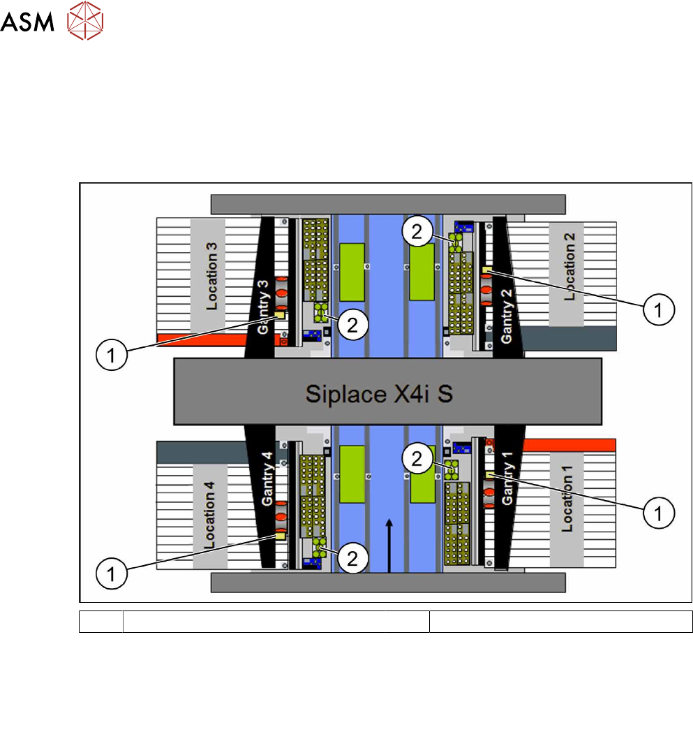
2.4.1 Possible configurations/required equipment - SIPLACE X4i S
SIPLACE X4i S – configuration 1
1 Pin picker left (4x) 2 W5 magazine (4x)
Notes:
●
3 tracks (locations 1 and 3) can not be
reached due to the pin picker
●
Table position 1 (inner)
●
One W5 magazine (per location).
●
2 dummy feeders
●
Gantry 1 to 4: pin picker left
●
One NC row
Parts required:
●
1x Smart Pin Support - pin picker – package – X4i S [00119994-xx]
– 4x Pin picker left [03089903-xx]
– 4x Smart Pin Support set 5 pins [00119995-xx] (=20pins)
●
4x Smart Pin Support magazine W5 [00119998-xx]
●
4x Spacer for SPS [03094012-xx]
●
2x Dummy feeder [00519876-xx] (for location 1 and3)