00197394-03_AI_Smart-Pin-Support_X-S_DE_EN.pdf - 第103页
3 Installation 3.2 Installation of Pin PIcker Assembly Instructions / Montageanleitung SIPLACE X-Series S Smart Pin Support 05/2019 103 3.2.4 Connecting the Compressed Air Supply Connection of the compressed air supply c…
3 Installation
3.2 Installation of Pin PIcker
102 Assembly Instructions / Montageanleitung SIPLACE X-Series S Smart Pin Support 05/2019
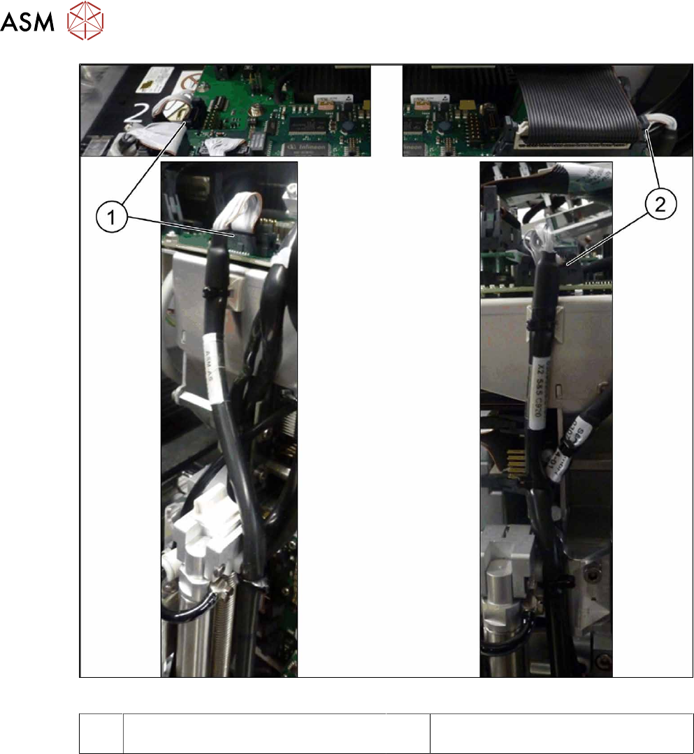
Fig.25: Connection on the head interface
1 Connection to the board "head interface
C700-L" (left) to connector X11
2 Connection to the board "head interface
C700-R" (right) to connector X13
► Connect the round cable to the head interface.
3 Installation
3.2 Installation of Pin PIcker
Assembly Instructions / Montageanleitung SIPLACE X-Series S Smart Pin Support 05/2019 103
3.2.4 Connecting the Compressed Air Supply
Connection of the compressed air supply can differ, depending on the head which is fitted.
CAUTION
Cable and hose path
► Make sure that the entry areas for the gantry buffer are kept free of cables and hoses.
These could be trapped otherwise.
► Use the pneumatic connection at the top right, on the compressed air distributor, par-
ticularly when a vacuum pump is fitted. There may not always be a compressed air
supply at other connections.
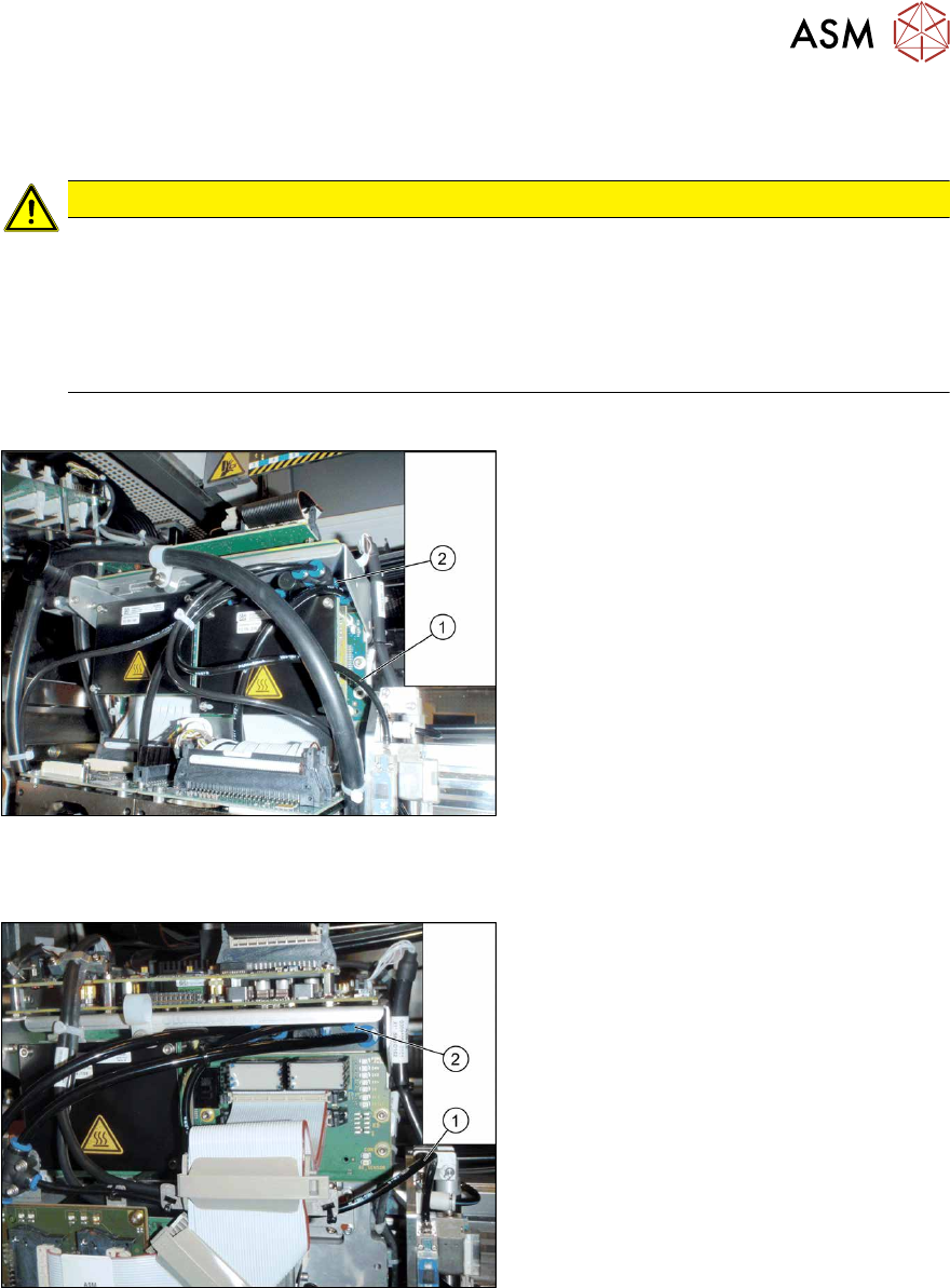
Connecting compressed air to a gantry with SIPLACE Twin
Fig.26: Connecting the compressed air with SIPLACE Twin
► Connect the pneumatic hose(1) for the
pin picker to the top right connection(2)
on the compressed air distributor. You
may need to use a T or Y piece for this.
Shorten the hoses to suitable lengths
for this.
► Fix the hose with cable ties.
Connecting compressed air to a gantry with SIPLACE C&P/CPP
Fig.27: Compressed air with SIPLACE C&P/CPP
► Connect the pneumatic hose(1) for the
pin picker to the top right connection(2)
on the compressed air distributor.
Shorten the hoses to suitable lengths
for this.
► Fix the hose with cable ties.
3 Installation
3.3 Installing the W5 magazine (SIPLACE X3 S, X4 S)
104 Assembly Instructions / Montageanleitung SIPLACE X-Series S Smart Pin Support 05/2019
3.3 Installing the W5 magazine (SIPLACE X3 S, X4 S)
See also
2 2.4 "Possible Configurations/Required Equipment" [}82]
3.3.1 Preparatory Steps
► The "Row 2 nozzle changer" option must be installed.
► If required, dismantle the row 1 nozzle changer for easier access. Read the service manual
for your machine for more information, if required.
3.3.2 Checking/Correcting the Vertical Distance
If you have not already done so, you need to check the height of the second NC row.
► For better access when measuring on the outer side, push the placement head inwards.
► Move the gantry so that the placement head is roughly on the planned NC position.
NOTICE
Avoid scratching the magnetic strip.
Make sure that the tip of the measuring scale does not touch the magnetic strip, as this
might scratch it!
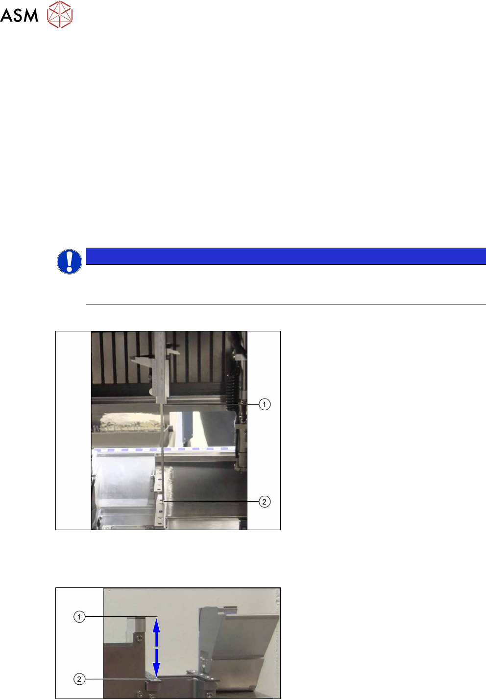
Checking the height of the second NC row
Fig.28: Height check (using the example of the holder for
second NC row)
► Check the height of the installed sup-
ports or holders for the second row.
► Position the measuring scale vertically
onto the top edge of the X axis lower
linear guide at (1) and measure the dis-
tance to the support or holder contact
surface (2).
Measured value: 150.0mm +/‑0.2mm
► If the distance is smaller, you will need
to remove the shim plates from under
the contact surfaces and repeat the
measurement.
Checking the height of the ASP support
Fig.29: Checking the height of the ASP support (using
example of SIPLACE X3 S/X4 S representing the measuring
principle)
If the height of the second NC row is cor-
rectly set to 150.0mm +/- 0.2 mm, you will
need to check the distance between the NC
and the ASP support.
► Position the measuring scale vertically
onto the contact surface of the NC (1)
and measure down to the ASP support
(2).
Measured value: 77mm +/‑0.2mm
► If the distance is outside the tolerance
range, insert or remove shim plates as
required.