00197394-03_AI_Smart-Pin-Support_X-S_DE_EN.pdf - 第114页
3 Installation 3.5 Installing the Q10 Magazine 114 Assembly Instructions / Montageanleitung SIPLACE X-Series S Smart Pin Support 05/2019 Fig.45: Data cable for NC 2 and SPS ► Locate the required cables. Four labeled dat…
3 Installation
3.5 Installing the Q10 Magazine
Assembly Instructions / Montageanleitung SIPLACE X-Series S Smart Pin Support 05/2019 113
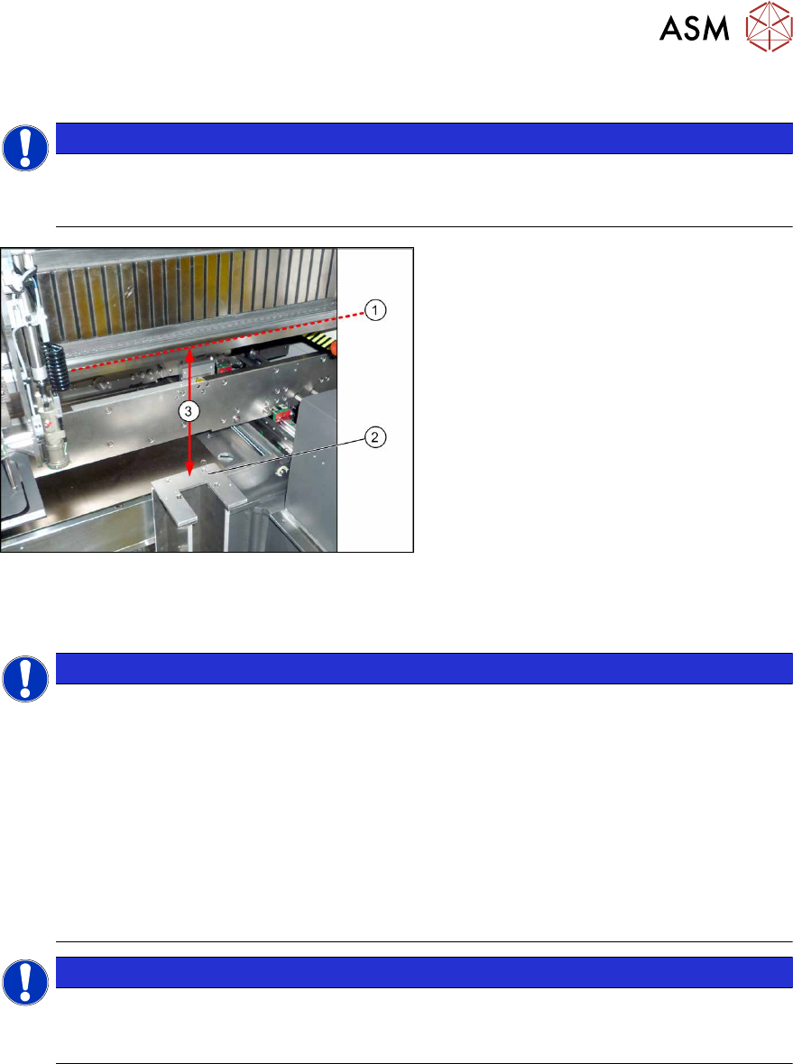
3.5.2 Checking/Correcting the Vertical Distance
NOTICE
Avoid scratching the magnetic strip.
Make sure that the tip of the measuring scale does not touch the magnetic strip, as this
might scratch it!
Fig.44: Checking the Height
► For measurement, push the gantry over
the magazine holder.
► Position the measuring scale vertically
onto the top edge (1)of the X axis lower
linear guide and measure the distance
to the support surface (2).
Measured value(3): 227.0mm +/‑0.2mm
► If the distance is outside the tolerance
range, insert or remove shim plates as
required.
3.5.3 Connecting the "Magazine Recognition" Board (If Present)
NOTICE
From SW 706.1 SP2
► Configuration of the magazines is performed automatically in machines before SW
706.1 SP2, using the "magazine recognition" board.
► If older machines with SPS are upgraded to a version equal to or higher than SW
706.1 SP2, the existing magazine configuration is kept in the software. If additional
magazines without board are fitted into these upgraded machines, these must be
manually configured via the software (Autoconfig).
► From SW 706.1 SP2, magazines can be fitted without the "magazine recognition"
function. In this case, the machine can only be configured manually via the software
(Autoconfig).
Proceed with chapter 3.3.4 "Assembling the W5 magazine" [}106] if this applies.
NOTICE
Configuring the Q 10 magazine
► If the Q10 magazine is fitted together with an MTC at location 2, the configuration is
always performed manually via the software.
3 Installation
3.5 Installing the Q10 Magazine
114 Assembly Instructions / Montageanleitung SIPLACE X-Series S Smart Pin Support 05/2019
Fig.45: Data cable for NC 2 and SPS
► Locate the required cables.
Four labeled data cables have been pre-
pared in the machine for the various config-
urations of NCs with and without Smart Pin
Support (SPS).
●
X1*a (NC 1)
●
X1*b (SPS (1) or NC 2 (without SPS))
●
X1*c (NC 2 with SPS)
●
X1*d (SPS2)
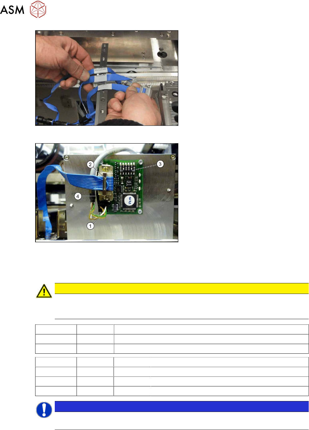
Fig.46: Board connection (using example of Q10)
► If not fitted, screw the board to the un-
derside of the magazine with four
M2.5x4 screws. The connection for the
flat ribbon cable should point towards
the angular metal bracket(4).
► Connect the power supply cable (1) to
connector X8 on the magazine board.
► Fit the strain relief for the voltage sup-
ply cable to the metal bracket and then
fix the cable into place.
► Connect the "NC SPS ribbon cable" (2)
to connector X6 on the board and
screw into place.
► Set the jumper (3) on the DIP
switchS1. (see below )
3.5.3.1 DIP Switch S1 - Jumper Assignment
CAUTION
Q10 magazine
If the Q10 magazine is fitted together with an MTC at location 2, the Q10 magazine is al-
ways configured manually via the software (autoconfig).
S1.1 S1.2 Magazine connected at
ON OFF NC connection 2
OFF ON NC connection 4
S1.4 S1.5 S1.6 Meaning
OFF OFF OFF Garage is switched off
OFF ON OFF Garage type Q10
X X ON Reserved
NOTICE
Jumper S1.3
Jumper S1.3 is not used.
3 Installation
3.6 Converting the nozzle station and the reject bin (SIPLACE X3 S, X4 S only)
Assembly Instructions / Montageanleitung SIPLACE X-Series S Smart Pin Support 05/2019 115
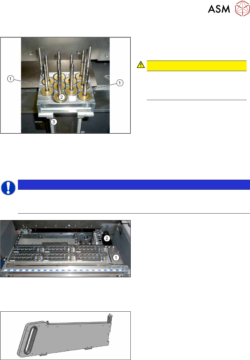
3.5.4 Assembling the Q10 magazine
Fig.47: Q10 magazine
► Position the magazine on the holder (3)
and screw into place with the fastening
screws(1).
CAUTION!
Observe the installation position.
The calibration garage (2) must be on
the side turned away from the con-
veyor.
.
3.6 Converting the nozzle station and the reject bin (SIPLACE
X3 S, X4 S only)
NOTICE
Assembly instructions
► For details, also read the assembly instructions for "NC row 2 / NC before MTC2 –
SIPLACE X‑SeriesS" [DE+EN:00197369‑xx].
Fig.48: Nozzle station and reject bin
► If present, the nozzle station and the
corresponding reject bin must be
moved from(1), further inwards to(2).
► Fit a cover plate at the previous
place(1).
► Repeat these steps, as required, for all
locations.
3.7 Inserting the dummy feeder
Fig.49: Dummy feeder
► SIPLACE X4S, X4iS: At locations 1
and3, fit the "COT-X filler piece with
fiducial 2slots" [00519876‑xx] to
track39.
This occupies tracks 38 and39.
► SIPLACE X3S: At locations 1, fit the
"COT-X filler piece with fiducial
2slots" [00519876‑xx] to track39.
This occupies tracks 38 and39.