00197394-03_AI_Smart-Pin-Support_X-S_DE_EN.pdf - 第106页
3 Installation 3.3 Installing the W5 magazine (SIPLACE X3 S, X4 S) 106 Assembly Instructions / Montageanleitung SIPLACE X-Series S Smart Pin Support 05/2019 3.3.3.1 DIP Switch S1 - Jumper Assignment S1.1 S1.2 Magazine co…
3 Installation
3.3 Installing the W5 magazine (SIPLACE X3 S, X4 S)
Assembly Instructions / Montageanleitung SIPLACE X-Series S Smart Pin Support 05/2019 105
3.3.3 Connecting the "Magazine Recognition" Board (If Present)
NOTICE
From SW 706.1 SP2
► Configuration of the magazines is performed automatically in machines before SW
706.1 SP2, using the "magazine recognition" board.
► If older machines with SPS are upgraded to a version equal to or higher than SW
706.1 SP2, the existing magazine configuration is kept in the software. If additional
magazines without board are fitted into these upgraded machines, these must be
manually configured via the software (Autoconfig).
► From SW 706.1 SP2, magazines can be fitted without the "magazine recognition"
function. In this case, the machine can only be configured manually via the software
(Autoconfig).
Proceed with chapter 3.3.4 "Assembling the W5 magazine" [}106] if this applies.
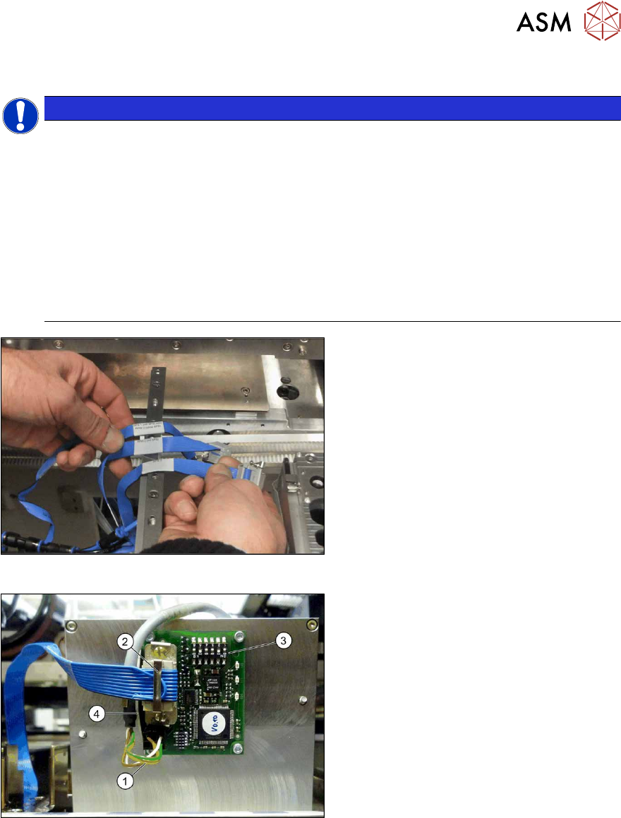
Fig.30: Data cable for NC 2 and SPS
► Locate the required cables.
Four labeled data cables have been pre-
pared in the machine for the various config-
urations of NCs with and without Smart Pin
Support (SPS).
●
X1*a (NC 1)
●
X1*b (SPS (1) or NC 2 (without SPS))
●
X1*c (NC 2 with SPS)
●
X1*d (SPS2)
Fig.31: Board connection (using example of Q10)
► If not fitted, screw the board to the un-
derside of the magazine with four
M2.5x4 screws. The connection for the
flat ribbon cable should point towards
the angular metal bracket(4).
► Connect the power supply cable (1) to
connector X8 on the magazine board.
► Fit the strain relief for the voltage sup-
ply cable to the metal bracket and then
fix the cable into place.
► Connect the "NC SPS ribbon cable" (2)
to connector X6 on the board and
screw into place.
► Set the jumper (3) on the DIP
switchS1. (see below )
3 Installation
3.3 Installing the W5 magazine (SIPLACE X3 S, X4 S)
106 Assembly Instructions / Montageanleitung SIPLACE X-Series S Smart Pin Support 05/2019
3.3.3.1 DIP Switch S1 - Jumper Assignment
S1.1 S1.2 Magazine connected at
ON OFF NC connection 2
OFF ON NC connection 4
S1.4 S1.5 S1.6 Meaning
OFF OFF OFF Garage is switched off
ON OFF OFF Garage type W5
X X ON Reserved
NOTICE
Jumper S1.3
Jumper S1.3 is not used.
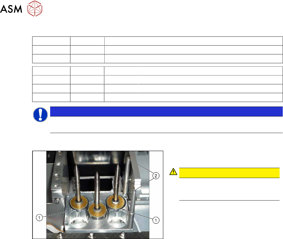
3.3.4 Assembling the W5 magazine
Fig.32: W5 magazine
► Fix the magazine into place with the
four fastening screws(1).
CAUTION!
Observe the installation position.
The calibration fiducials (2) need to be
on the right-hand side.
.
3 Installation
3.4 Installing the W5 magazine (SIPLACE X4i S)
Assembly Instructions / Montageanleitung SIPLACE X-Series S Smart Pin Support 05/2019 107
3.4 Installing the W5 magazine (SIPLACE X4i S)
See also
2 2.4 "Possible Configurations/Required Equipment" [}82]
3.4.1 Preparatory Steps
► If required, dismantle the row 1 NC for easier access. Read the service manual for your
machine for more information, if required.
3.4.2 Fitting the Support Plate
If two W5 magazines are fitted at one location, the H-shaped NC ASP support plate for NC row 2
will be fitted between the first NC row and the nozzle station.
Parts required
Quantity Designation Item number
1 NC ASP support plate for row 2 03090087-xx
4 M4x10 03023262-xx
Installation
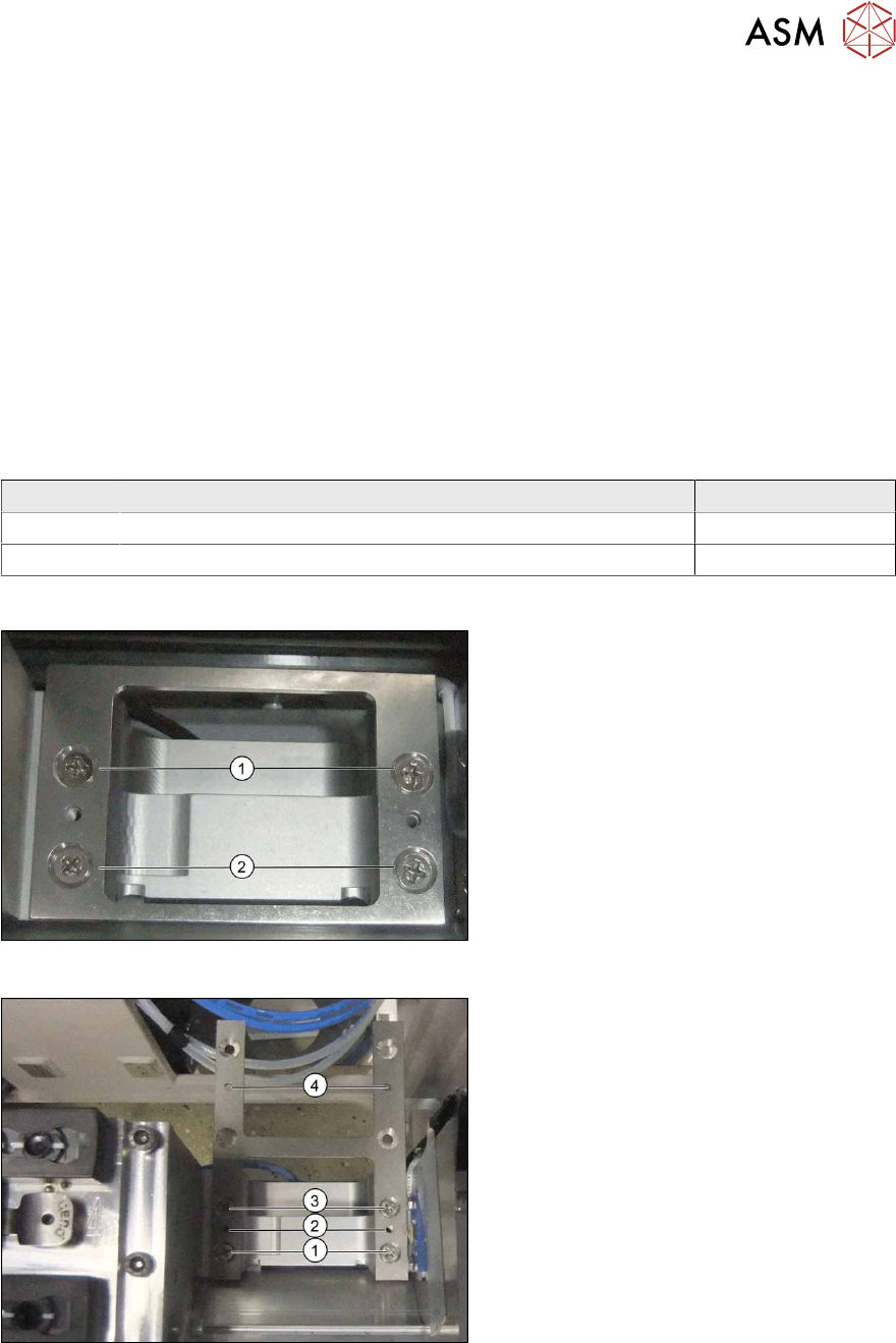
Fig.33: Short support plate
► Remove the short support plate before
installing the H-shaped support plate.
► Remove the screws at (1) and (2).
Fig.34: H-shaped support plate
► Use the four screws to fix the support
plate at (1) and (3).
The points marked (2) and (4) are reserved
for fastening the magazines.
► Fix the magazine for the first NC row to
(2) and that for NC row 2 to (4).