c900795.R02_EN.pdf - 第102页
4 Electrical Section 4-28 Control Board Handling Control Board Note the followings when handl ing PC boards. z Do not touch control boards by wet hands. z Do not handle control boards where t here are metal chi ps around…

4 Electrical Section
4-27
Diagnostic
Code
Meaning
Diagnostic
Code
Meaning
80h Disable onboard Super I/O ports and IRQs B0h Check for errors
81h Late POST device initialization B1h Inform RomPilot about the end of POST.
82h Detect and install external RS232 ports B2h POST done - prepare to boot operating system
83h Configure non-MCD IDE controllers B4h One short beep before boot
84h Detect existence of parallel ports B5h Terminate QuietBoot
85h Checking for PnP ISA devices B6h Check password
86h Re-initialize onboard I/O ports B7h Initialize ACPI-BIOS
87h Configure Motherboard Configurable Devices B9h Clear Screen
88h Initialize BIOS Data Area BAh Initialize SMBIOS
89h Enable Non-Maskable Interrupts (NMIs) BCh Clear parity checkers
8Ah Initialize Extended BIOS Data Area BDh Display MultiBoot menu
8Bh Test and initialize PS/2 mouse BEh Clear screen
8Ch Initialize floppy controller BFh Check virus and backup reminders
8Fh Determine number of ATA drives C0h Try to boot with INT 19
90h Initialize hard-disk controllers C1h Initialize POST Error Manager (PEM)
91h Initialize local-bus hard-disk controllers C2h Initialize error logging
92h Jump to UserPatch2 C3h Initialize error display function
93h Build MPTABLE for multi-processor boards C4h Initialize system error handler
95h Install CD ROM for boot C5h PnP dual CMOS
96h Clear huge ES segment register C6h Initialize note dock
97h Fixup Multi Processor table C7h Initialize note dock rate
98h Search for option ROMs. One long, two short beeps on
checksum failure
C8h
Force check
99h Check for SMART Drive C9h Extended checksum
9Ch
Set up Power Management
CBh
Redirect Int 13h to Memory Technologies Devices
such as ROM, RAM,PCMCIA, and serial disk
9Dh Initialize security engine CCh Redirect Int 10h to enable remote serial video
9Eh Enable hardware interrupts CDh Redirect Int 15h to enable remote keyboard
9Fh Determine number of ATA and SCSI drives CEh Initialize digitizer and display message
A0h Test Real Time Clock interrupt D2h Unknown interrupt
A2h Check key lock E0h Check memory mounting
A4h Initialize Typematic rate
A8h Erase F2 prompt
AAh Scan for F2 key stroke
ACh Enter SETUP
AEh Clear Boot flag

4 Electrical Section
4-28
Control Board
Handling Control Board
Note the followings when handling PC boards.
z Do not touch control boards by wet hands.
z Do not handle control boards where there are metal chips around.
z Wear an antistatic wrist strap and connect it with any metal part of the machine.
z Do not put an electrical board on the place where may cause the short circuit.
4 Electrical Section
4-29
Adjustment of Board Detection Sensors
This section explains how to adjust the sensitivity of the board detection sensors.
● LE6-M6547-00X PHOTO SENSOR E3Z-LS81 (OMRON)
z Entrance sensor
z Exit sensor
z Exit buffer arrival sensor
■ Adjusting Method
① Place a PCB on the conveyor belt in the direction in which PCBs will be placed for actual production
operation.
② Turn the sensor’s sensitivity volume counter-clockwise (toward “min”) as far as it will go, to set the
sensitivity to the minimum level.
*The volume can be turned 3/4 turns. Turning it clockwise (toward “max”) increases the sensitivity
and turning it counter-clockwise (toward “min”) decreases it.
③ With the PCB detected by the sensor, turn the volume clockwise (toward “max”) gradually, up to the
point (A) where the orange LED (operation indicator) begins to light up.
④ Remove the PCB and turn the volume clockwise (toward “max”), up to the point (B) where the orange
LED begins to light up. (If the orange LED does not light up even if the volume is turned clockwise as
far as it will go, the position to which the volume has been turned clockwise as far as it will go will be
considered to be position (B).)
⑤ The center position between the positions (A) and (B) is set as the adjustment position. With the PCB
detected at that position, check that both orange and green LEDs light up at the same time. Also check
that only the green LED lights up when the PCB is removed.
⑥ When the conveyor cover is provided because of the safety spec., attach a black rubber sheet
(LG0-M9AA1-00X GOM) to the sensor detection position on the bottom of the cover to prevent false
detection.
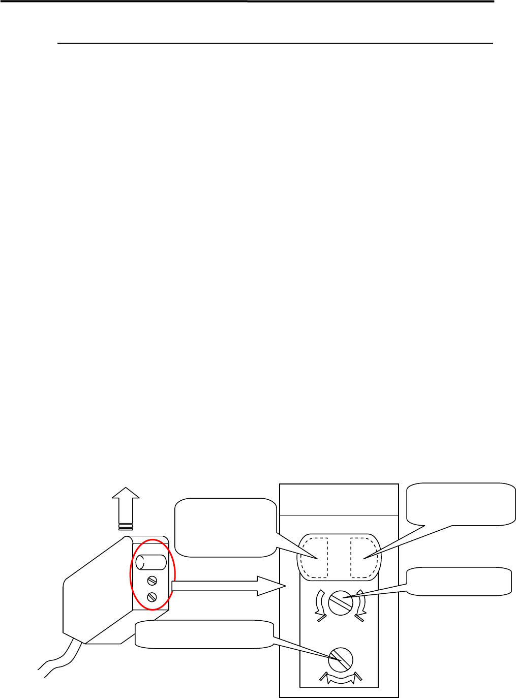
NOTE: Make sure that the operation selector switch is set to “L” (ON when light is entered).
max min
DL
Sensor emitting direction
Enlarged View of Sensor
(Shown in upside down direction)
Operation indicator
(Orange LED)
Operation-stable
indicator
(Green LED)
Sensitivity volume
Operation selector switch