c900795.R02_EN.pdf - 第79页
4 Electrical Section 4-5 Serial I/O ■ Serial I/O List Serial DO – Device 1, 3, 7, 9 Serial DI – Device 2, 4, 8, 10 Action: ① Click the cell corresponding to t he desired actuator. ② At the same time you click the cell, t…

4 Electrical Section
4-4
Signal Output Control
The Signal Output (Control) window serves as controls to turn on or off actuators. “1” in the window
indicates On state, “0” Off state. “0” and “1” toggle as you click on it, and the corresponding actuator is
turned on or off simultaneously. This operation allows you to check actuator movement in troubleshooting.
When an actuator moves properly in this operation, its sensor responds and the Signal Input (Monitor)
window shows the real-time result. The combination of an address and bit number (0-7) represents a signal.
The name of each signal is shown in the Details tab.
Turning on/off signal output in the Signal Output (Control) window allows an actuator to move. When
executing this operation, do not stick head, hands, or other parts of the body inside the unit. Serious injury
can result. Also make sure non-operators are a safe distance from the unit.
Before performing signal output on/off operation, make sure no foreign obstacles are left in the unit or tray
feeder. Otherwise, costly machine damage can occur.
Menu: Manual>Signal I/O>SignalOutput(Control)
■Digital Output (List) ・・・Not Use
■Digital Output (Details)・・・Not Use
Warning
Caution
4 Electrical Section
4-5
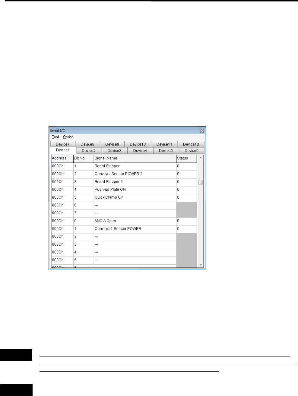
Serial I/O
■ Serial I/O List
Serial DO – Device 1, 3, 7, 9
Serial DI – Device 2, 4, 8, 10
Action:
① Click the cell corresponding to the desired actuator.
② At the same time you click the cell, the display changes 1(On) or 0(Off), and the actuator moves
accordingly.
Example:
■ Moving Up and Down the Board Stopper
① Select Manual> Signal I/O to open [Serial I/O] window.
② Select [Device3] tab.
③ Click [State] of [Board Stopper Up A] cell, Status changes “0” to “1” and the board stopper lifts.
At this time, confirm that State of [Board Stopper Up A (0010h)] in [Device4] switches from “0” to “1”.
④ To move down the board stopper, click [State] of [Board Stopper Up A] in [Device3].
And State changes “1” to “0”. At this time, State of [Board Stopper Up A (0010h)] in [Device4] switches
from “1” to “0”.
Turning on/off signal output in the Signal Output (Control) window allows an actuator to move. When
executing this operation, do not stick head, hands, or other parts of the body inside the unit. Serious injury
can result. Also make sure non-operators are a safe distance from the unit.
Before performing signal output on/off operation, make sure no foreign obstacles are left in the unit or tray
feeder. Otherwise, costly machine damage can occur.
Warning
Caution
4 Electrical Section
4-6
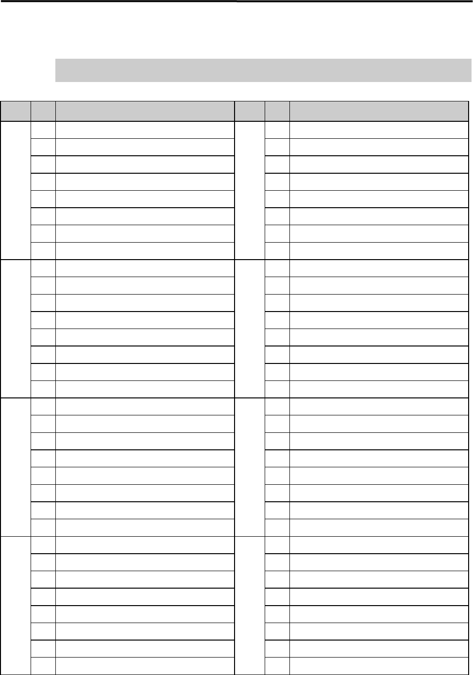
Serial DO Map
Turning on/off in the serial DO Map allows an actuator to moves.
Please be confirmed safety before exciting this function.
■ Device 1
Address
Bit
No.
Signal Name Address
Bit
No.
Signal Name
0000h 0 READY SW (F) 0004h 0
Signal Tower 1 On
1 RESET SW (F) 1
Signal Tower 2 On
2 START SW (F) 2
Signal Tower 3 On
3 STOP SW (F) 3
Signal Tower 4 On
4 CLEAR SW (F) 4
5 5
WARING SOUND
6 6
HAZARD SOUND
7 DOCKING SW (F) (Right Front) 7
UPS Shout down
0001h 0 0005h 0
READY Output
1 1
BOARD AVAILABLE Output
2 2
3 3
4 4
5 5
6 6 Trigger 1 Output Place Bit 0
7 7 Trigger 1 Output Place Bit 1
0002h 0 READY SW (R) 0006h 0
Safety Relay Rest
1 RESET SW (R) 1
Front Cover Lock
2 START SW (R) 2
Rear Cover Lock
3 STOP SW (R) 3
4 CLEAR SW (R) 4
5
5
Internal Illumination ON
6
6
SERVO ON Permission 1
7 DOCKING SW (Left Rear) 7
SERVO ON permission 2
0003h 0 0008h 0
1
1
Feeder Bank Board Power Supply (Left Front) ON
2
2
3 CTF (R)/(Right Rear) Servo Power Supply 3
Feeder Bank Power (Left Front) 5V ON
4 4
5 5 Feeder Bank Power (Left Front) 24V ON
6 6 Feeder Bank Board Power Supply (Left Rear) ON
7 7 Feeder Bank Board Power Supply (R) (Right Rear ON