c900795.R02_EN.pdf - 第13页
Contents 1 Installa tion ................................................................................................... 1-1 Installation of Unit ......................................................................…
10
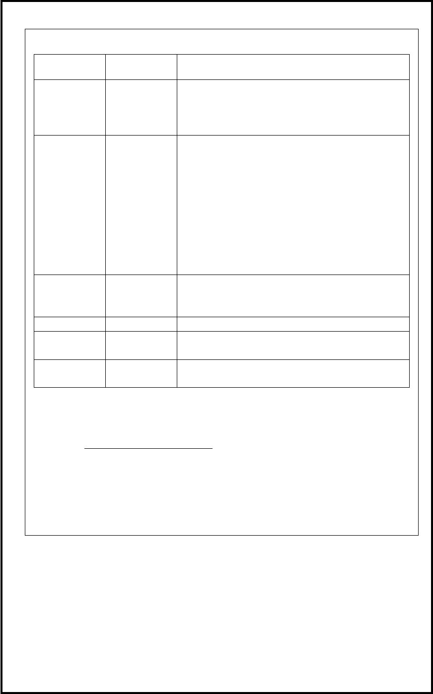
Name Use Main Component
Shock Watch
(Label Type)
Shock
Detecting
Instrument
Paper Label applied acrylic adhesive
Clip:Polystyrene(PS)
Paper Liner
Glass Tube
Tilt Sensor Tilt ( turnover
and drop)
detecting
instrument
Surface File:Polypropylene(PP)and Rubber Pressure
Sensitive Adhesive
Typographical Display:Pigment +Plastics
Surface Paper :Pulp
Base Material:Cellulose
Content of Detection Agent :Micro Beads Silica Gel
3A
Colorant of Detection Agent :Food Red (Blue #1)
Rock Pin:Stainless Steel(SUS301)
Surface Tape:Polyester+Acrylic Adhesive
Stretch File Prevention of
dust and
contamination
Polyethylene(PE)
Bubble Wrap
Polyethylene(PE)
Antitarnish
Paper
Cushioning Craft Paper
Volatile Corrosion Inhibitor
Banding Band To Fix
Movable Parts
Nylon 66(PA66)
■Others
• A variety of information related to our products is published in our home page. Please be
obtained latest information by checking our home page periodically
URL: http://www.yamaha-motor.co.jp
• Content of this manual may be changed without notice.

Contents
1 Installation ................................................................................................... 1-1
Installation of Unit .............................................................................................................. 1-2
Environmental Requirements .................................................................................... 1-2
How to Hoist Unit ..................................................................................................... 1-3
Production Line ........................................................................................................ 1-4
Installing Unit ........................................................................................................... 1-5
LCD Monitor and Installation of Balancer ............................................................... 1-9
Air and Power Cable Lead-In ........................................................................................... 1-10
Supplementary Explanation for Installation ........................................................... 1-11
Removal of Rust Inhibiting Grease ......................................................................... 1-13
Linkage of D10 and the loader .......................................................................................... 1-15
Pre-Process and Post-Process of D10 ............................................................................... 1-16
Connecting Pre-Process and Post-Process .............................................................. 1-16
Sequence of Receiving PC board (Standard spec.) ................................................. 1-17
Sequence of Sending PC board (Standard sepc.) .................................................... 1-18
Sequence of Receiving PC board (SMEMA Interface spec.) ................................. 1-19
Sequence of Sending PC board (SMEMA Interface spec.) .................................... 1-20
2 Periodical Checks ....................................................................................... 2-1
Daily Checks ....................................................................................................................... 2-2
Visual Check ............................................................................................................. 2-2
Manual Check ........................................................................................................... 2-3
Monthly Check.................................................................................................................... 2-4
3 Mechanical Section .................................................................................... 3-1
Head Manifold Section ....................................................................................................... 3-2
Head Manifold Section ....................................................................................................... 3-3
Inspection for Head/Nozzle Clogging and Solenoid Valve Breakdown ............................. 3-4
Assembling STD. DP HEAD .............................................................................................. 3-5
Assembling SCREW DP HEAD......................................................................................... 3-7
Installing O-RING on SCREW POMP ..................................................................... 3-8
Assembling STD DP ROTATION NOZ. ......................................................................... 3-10
Create Dispense Data .............................................................................................. 3-14
Installing the dispensing head ........................................................................................... 3-16
Filling the screw pump ...................................................................................................... 3-20
Camera .............................................................................................................................. 3-22
Mirror and lens of camera ....................................................................................... 3-22
Cleaning of Teach Camera ...................................................................................... 3-22
Cleaning of Lens Filter ........................................................................................... 3-22
Lubrication ........................................................................................................................ 3-23
Lubrication Points ................................................................................................... 3-23
Specified Lubricants ............................................................................................... 3-30
Installing the paper roll at the Dot Station ........................................................................ 3-31
4 Electrical Section ........................................................................................ 4-1
Signal I/O ............................................................................................................................ 4-2
Signal Input Monitor ................................................................................................. 4-2
Signal Output Control ............................................................................................... 4-4
Serial I/O ................................................................................................................... 4-5
Serial DO Map .......................................................................................................... 4-6
Serial DI Map ......................................................................................................... 4-15
System Box Assembly ...................................................................................................... 4-21
Serial I/O Operation Check LED ............................................................................ 4-22
Vision Operation Check LED ........................................................................................... 4-23
Motion Port Operation Check LED .................................................................................. 4-24
Motion Operation Check LED .......................................................................................... 4-25
Control Board ................................................................................................................... 4-28
Adjustment of Board Detection Sensors ........................................................................... 4-29
Cautions about overall electrical items ............................................................................. 4-31
Computer Virus Prevention and Treatment ...................................................................... 4-32
5 Materials ...................................................................................................... 5-1
Standard Accessories .......................................................................................................... 5-2
Replacement Parts ............................................................................................................... 5-3
Conveyor Belt List .................................................................................................... 5-4
Nozzle 5-5
Air Circuit Diagram .................................................................................................. 5-6