c900795.R02_EN.pdf - 第98页
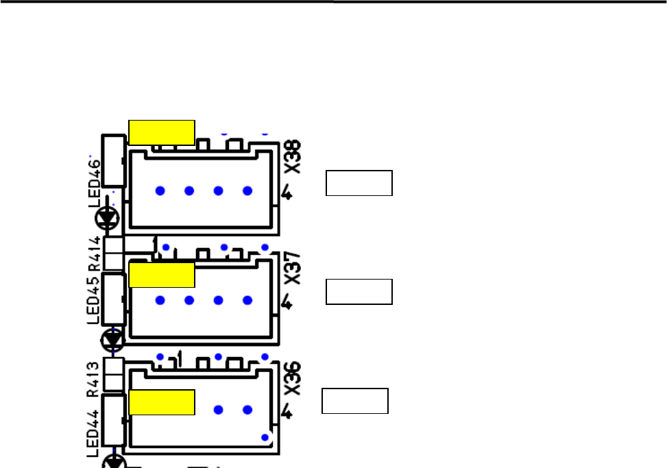
4 Electrical Section 4-24 Motion Port Operation Check LED z LED44 and 45 will be lit (Yellow) when receiving response data from the servo amplifiers. LED46 LED45 LED44 Port2 Port1 Port0 CTF Z & T Axes X&Y Axes
4 Electrical Section
4-23
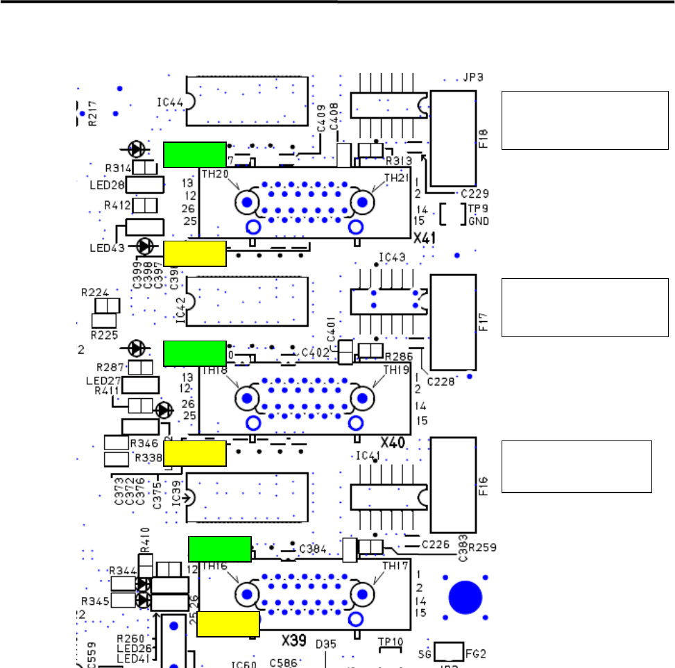
Vision Operation Check LED
F18:Fixed Camera(Rear)
+12V Fuse
(Socket Insert Type)
F17:Fixed Camera (Front)
+12V Fuse
(Socket Insert Type)
F16:Teach Camera
+12V Fuse
(Socket Insert Type)
LED28
LED43
LED27
LED26
LED42
LED41
z +12 V is supplied to Cameras, then LED26 (Teach Camera), LED26 (Fixed Camera Front) and LED
28 (Fixed Camera Rear) will be lit (Green).
z LED will be lit (Yellow) when receiving Image Data.
LED41; Teach Camera
LED42; Fixed Camera Front
LED43; Fixed Camera Rear
4 Electrical Section
4-24
Motion Port Operation Check LED
z LED44 and 45 will be lit (Yellow) when receiving response data from the servo amplifiers.
LED46
LED45
LED44
Port2
Port1
Port0
CTF
Z & T Axes
X&Y Axes
4 Electrical Section
4-25
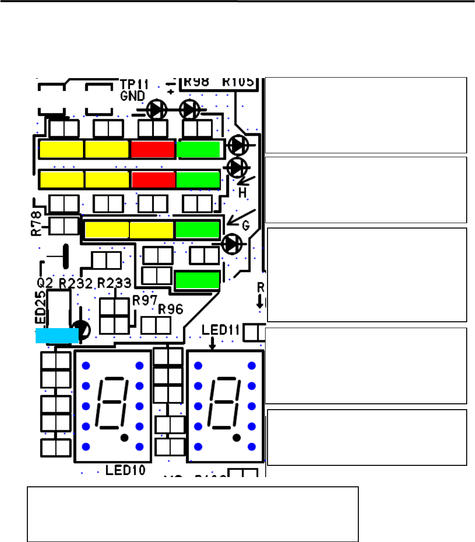
Motion Operation Check LED
LED6
LED9
LED8
LED7
LED4
LED5
LED3
LED20
LED22
LED24
LED21
LED23
LED25
If ATX power supply voltage is normal, the
below LEDs will be lit .
LED6 +5V Standby
LED9 +3.3V
LED8 +5V
LED7 +12V
LED4 (Red) will be lit in power saving mode.
LED5 (Red) will be lit if temperature of CPU
module is abnormal.
LED 3(Yellow) will light when accessing HDD
Loading data for each FPGA has been
succeeded and communication has been
established after power on, the below
LED will be lit.
LED20 Vision
LED22 Motion
LED24 Serial I/O
The below LED will be lit (Yellow) during
DMA transfer
LED21;Vision , Vision Data DMA
LED23; Motion, Axes Data DMA
*Note; LED23 looks like being lit if the system
has been booted up normally.
LED25 (Blue) is blinking quickly if the system
is normal
If LED25 (Blue) is lit or blackout if the system
is abnormal.
Seven Segment LED; LED10 – High Order, LED11-Low Order
After Windows has booted up normally, “c0” will be shown on seven segments.
Details of other cods shown in seven segments are mentioned in the next page.