c900795.R02_EN.pdf - 第117页
Index A Air filter, 3-3 Air Passage, 3-3 C Camera, 3-22 Control boards, 4-28 D Daily checks, 2-2 DI Monitor, 4-12 Digital Out put, 4-4 E Environmenta l requireme nts, 1-2 H Head Manifold Section, 3-3 I Inspection for Hea…
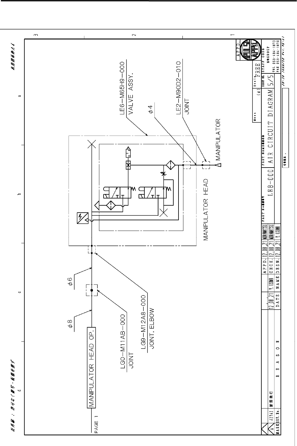
5 Materials
5-10
Manipulator OP
Index
A
Air filter, 3-3
Air Passage, 3-3
C
Camera, 3-22
Control boards, 4-28
D
Daily checks, 2-2
DI Monitor, 4-12
Digital Output, 4-4
E
Environmental requirements, 1-2
H
Head Manifold Section, 3-3
I
Inspection for Head/Nozzle Clogging and
Solenoid Valve Breakdown, 3-4
Installation, 1-2
L
Loader installation, 1-15
Lubricants, 3-30
Lubrication, 3-23
M
Manual check, 2-3
Monthly check, 2-4
N
Nozzle Holder, 3-29
Nozzle, Locate Pin, Pushup Pin, etc, 5-2
P
Pre-process and post-process, 1-16
Production line, 1-4
R
Replacement Parts, 5-3
S
SCREW DP HEAD, 3-7
SCREW POMP, 3-8
Serial I/O, 4-5
Signal I/O, 4-2
Signal Input Map, 4-11
Signal Input Monitor, 4-2
Signal Output Control, 4-4
Signal Output Control window, 4-4
STD DP ROTATION, 3-10
STD. DP HEAD, 3-5
V
Vacuum generator, 3-3
visual check, 2-2

YAMAHA SMT Assembly System
127 Toyooka, Kita-ku, Hamamatsu, Shizuoka 433-8103, Japan
YAMAHA MOTOR CO., LTD IM OPERATIONS
Telephone 81-53-525-7061 Facsimile 81-53-525-8351
All rights reserved. No part of this publication may be reproduced in any form without the permission
of YAMAHA MOTOR CO., LTD. Information furnished by YAMAHA in this manual is believed to be reliable.
However, no responsibility is assumed for possible inaccuracies or omissions.
If you find any part unclear in this manual, please contact YAMAHA or YAMAHA sales representatives.
Version 900795.R02.EN
Service Manual April, 2016