c900795.R02_EN.pdf - 第30页
1 Installation 1-16 Pre-Process and Post-Process of D10 Connecting Pre-Process and Post-Process When using other manufacturer’s unit s as the pre-process or post-process, connect them as shown i n the below diagram. No-v…

1 Installation
1-15
Linkage of D10 and the loader
There is an entrance sensor at the entrance of the unit. If the loader is installed upstream of the unit, the
entrance sensor must be moved to avoid interruption with the loader.
After the sensor has been moved, align the conveyors for smooth board transfer.
1 Installation
1-16
Pre-Process and Post-Process of D10
Connecting Pre-Process and Post-Process
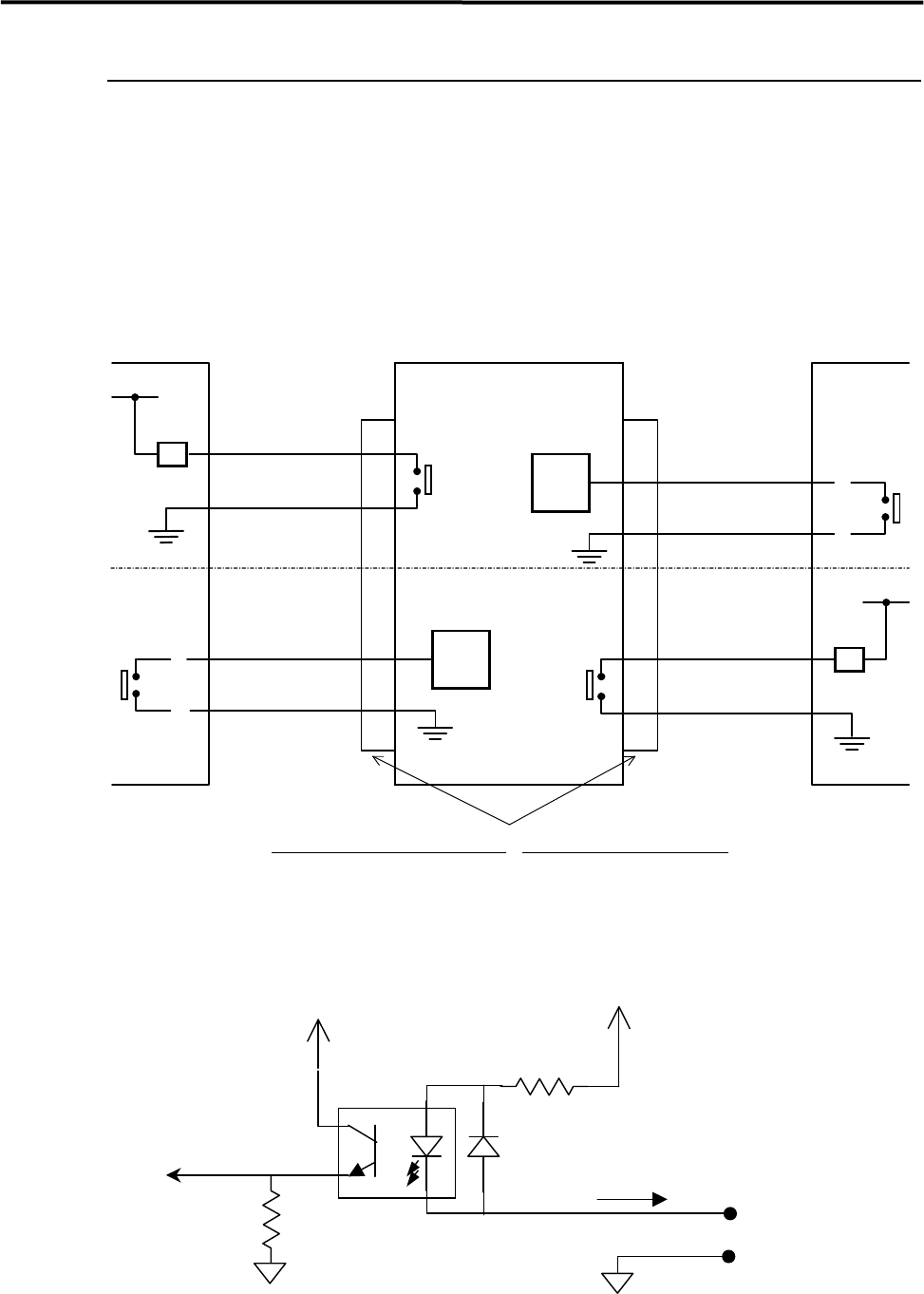
When using other manufacturer’s units as the pre-process or post-process, connect them as shown in the
below diagram. No-voltage output (relay) is recommended for post-process.
Standard spec. : Upper half of the diagram.
SMEMA Interface spec. : Whole diagram.
+24V
DI
+5V
2.04 k(1/4W*3)
HCPL-181
Approx. 11mA
2.2 k
(for NPN)
*INPUT CIRCUIT
*INPUT CIRCUIT
NOT READY
2
1
CN2 CN1
Post-process
Connector (Cable side)
AMP
206044-1(Plug)
66099-2 or equivalent (Pin)
206070-1(Cable clamp)
Connector (Mounter side)
AMP
206043-1(Receptacle)
Pre-process
MACHINE
NOT READY
*INPUT CIRCUIT
BOARD
DC30V 1A or less
AC100V 0.5A
or l ess
RELAY
RELAY
MACHINE
BOARD
A
VAILABLE
3
4
A
VAILABLE
2
1
3
4
1 Installation
1-17
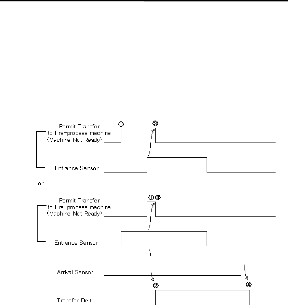
Sequence of Receiving PC board (Standard spec.)
① When the unit is ready to receive PC board, Permit Transfer (Machine Not Ready) is sent to
Pre-process machine.
② The transfer belt will be activated when the Permit Transfer and the Entrance Sensor turn on.
③ The Permit Transfer will be sent-off when Entrance Sensor turns on.
④ The transfer belt will be deactivated when the Arrival Sensor turns on.
⑤ “Conveyor Trouble” error happens if the Arrival Sensor does not turn on or the Entrance Sensor does
not turn off within 10 seconds after the transfer belt was activated.
⑥ Pressing START button restarts the operation paused by the error.