c900795.R02_EN.pdf - 第12页
10 Name Use Main Component Shock Watch (Label Type ) Shock Detecting Instrument Paper Label applied acryli c adhesive Clip : Polystyrene ( PS ) Paper Liner Glass Tube Tilt Sensor Tilt ( turnover and drop) detecting instr…
9
The lithium battery is used in XIO board.
The expected life time is two years (operating atmosphere temperature 23℃) .
If the battery runs out, the date and time shown in the monitor will be reset.
Please contact us or our distributor, replacement of the lithium battery will be done by our service
engineer.
If the removed lithium battery is discarded by customer, do not discard it as incombustible.
The electrical terminals of the battery have to be insulated by some tapes and so on, and then
should be discarded or recycled following law, code and regulation of your country.
* The lithium battery might heat, fire or burst if the electrical terminals short.
When the unit is exported to oversea, various kinds of packaging materials are used.
Please dispose or recycle packaging materials following law, code and regulation of your
country.
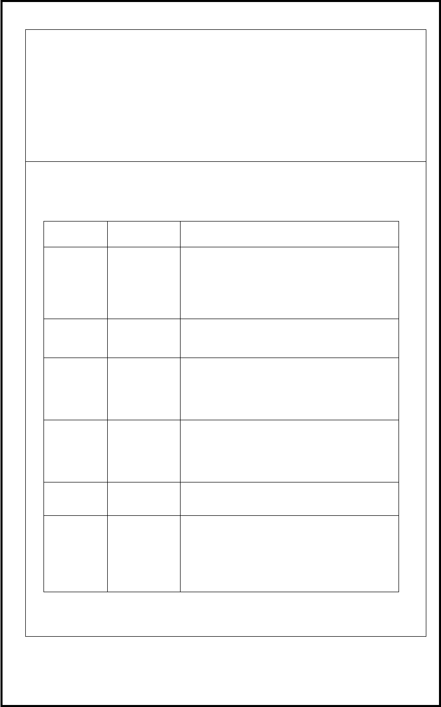
Components of packaging material are shown in the below table.
Name Use Main Component
Barrier Film Damp-proof
and Antirust
Packaging
Material
Polyethylene Telephthalate(PET)
Polyethylene(PE)
Polyethylene Cloth(PE)
LL Film:Ethylene・1-Butene Copolymer
HIPLE ACE Strengthened
Cardboard
Paper (Cellulose Fiber Aggregation)
Starch
Dick Estelle
Band
Packaging
Material for
Strengthened
Cardboard
Polyethylene Telephthalate(PET)
Pigment・Approx.0.2%
Carbon Black・Approx.0.2%
Dick
PP Band
Light Weight
Packaging
Band
Polypropylene(PP)
Calcium Carbonate・3%
Pigment・Approx.0.2%
Carbon Black・Approx.0.4%
PP Band
Clip
PP Band Clip
Polypropylene(PP)
Sun Dry
(desiccant)
Damp-proof,
Antirust and
Dew
Condensation
Prevention
Calcium Chloride
Non-woven fabric cloth
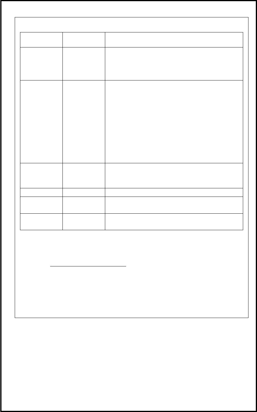
10
Name Use Main Component
Shock Watch
(Label Type)
Shock
Detecting
Instrument
Paper Label applied acrylic adhesive
Clip:Polystyrene(PS)
Paper Liner
Glass Tube
Tilt Sensor Tilt ( turnover
and drop)
detecting
instrument
Surface File:Polypropylene(PP)and Rubber Pressure
Sensitive Adhesive
Typographical Display:Pigment +Plastics
Surface Paper :Pulp
Base Material:Cellulose
Content of Detection Agent :Micro Beads Silica Gel
3A
Colorant of Detection Agent :Food Red (Blue #1)
Rock Pin:Stainless Steel(SUS301)
Surface Tape:Polyester+Acrylic Adhesive
Stretch File Prevention of
dust and
contamination
Polyethylene(PE)
Bubble Wrap
Polyethylene(PE)
Antitarnish
Paper
Cushioning Craft Paper
Volatile Corrosion Inhibitor
Banding Band To Fix
Movable Parts
Nylon 66(PA66)
■Others
• A variety of information related to our products is published in our home page. Please be
obtained latest information by checking our home page periodically
URL: http://www.yamaha-motor.co.jp
• Content of this manual may be changed without notice.

Contents
1 Installation ................................................................................................... 1-1
Installation of Unit .............................................................................................................. 1-2
Environmental Requirements .................................................................................... 1-2
How to Hoist Unit ..................................................................................................... 1-3
Production Line ........................................................................................................ 1-4
Installing Unit ........................................................................................................... 1-5
LCD Monitor and Installation of Balancer ............................................................... 1-9
Air and Power Cable Lead-In ........................................................................................... 1-10
Supplementary Explanation for Installation ........................................................... 1-11
Removal of Rust Inhibiting Grease ......................................................................... 1-13
Linkage of D10 and the loader .......................................................................................... 1-15
Pre-Process and Post-Process of D10 ............................................................................... 1-16
Connecting Pre-Process and Post-Process .............................................................. 1-16
Sequence of Receiving PC board (Standard spec.) ................................................. 1-17
Sequence of Sending PC board (Standard sepc.) .................................................... 1-18
Sequence of Receiving PC board (SMEMA Interface spec.) ................................. 1-19
Sequence of Sending PC board (SMEMA Interface spec.) .................................... 1-20
2 Periodical Checks ....................................................................................... 2-1
Daily Checks ....................................................................................................................... 2-2
Visual Check ............................................................................................................. 2-2
Manual Check ........................................................................................................... 2-3
Monthly Check.................................................................................................................... 2-4
3 Mechanical Section .................................................................................... 3-1
Head Manifold Section ....................................................................................................... 3-2
Head Manifold Section ....................................................................................................... 3-3
Inspection for Head/Nozzle Clogging and Solenoid Valve Breakdown ............................. 3-4
Assembling STD. DP HEAD .............................................................................................. 3-5
Assembling SCREW DP HEAD......................................................................................... 3-7
Installing O-RING on SCREW POMP ..................................................................... 3-8
Assembling STD DP ROTATION NOZ. ......................................................................... 3-10
Create Dispense Data .............................................................................................. 3-14
Installing the dispensing head ........................................................................................... 3-16
Filling the screw pump ...................................................................................................... 3-20
Camera .............................................................................................................................. 3-22
Mirror and lens of camera ....................................................................................... 3-22
Cleaning of Teach Camera ...................................................................................... 3-22
Cleaning of Lens Filter ........................................................................................... 3-22
Lubrication ........................................................................................................................ 3-23
Lubrication Points ................................................................................................... 3-23
Specified Lubricants ............................................................................................... 3-30
Installing the paper roll at the Dot Station ........................................................................ 3-31