c900795.R02_EN.pdf - 第54页
3 Mechanical Section 3-16 Installing the dispensing head The procedure for installing the dispense head on t he machine is given bel ow. ■ Installing the magnet set for remaining am ount detection ■ Installing the syring…
3 Mechanical Section
3-15
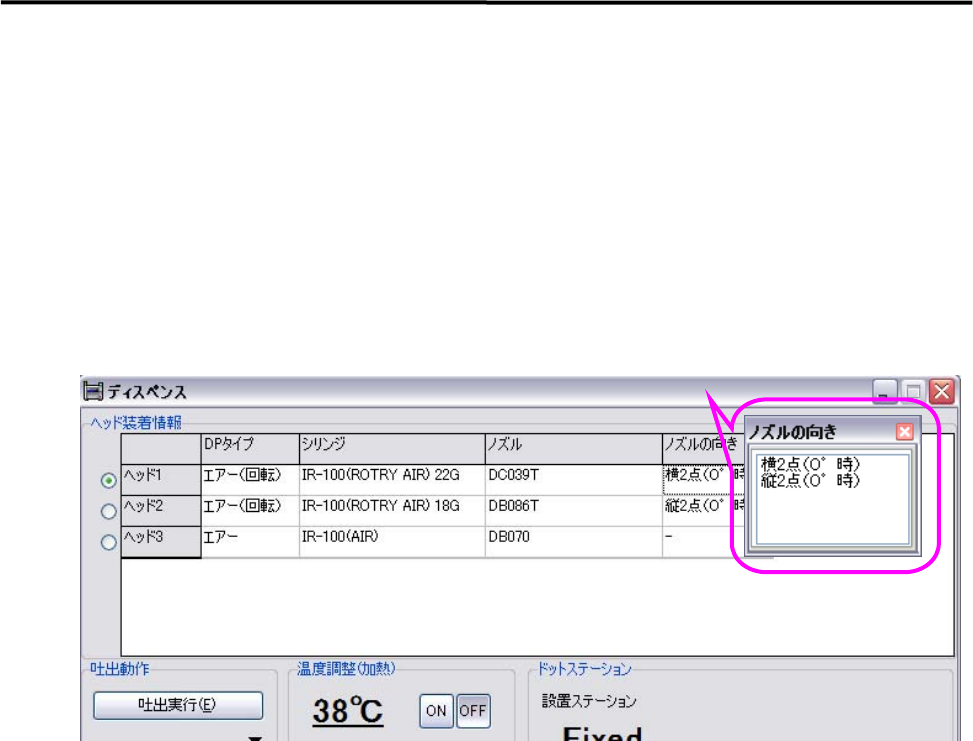
3. Manual > Dispense > Head Configuration
3-1. Click the right muse bottom in DP type and then select “Air (Rotation)”.
3-2. Click the right muse bottom in Syringe and Nozzle, and then select data used. In addition, either “Twin
in Vertical” or “Twin in Horizontal” should be selected for Nozzle Angle.
The angle added theta axis in Dispense & Mark Data to theta offset in Dispense Data will be 0 degree.
The nozzle direction does not matter when the nozzle is installed on the head, because the angle will be
adjusted according to the current situation.
3 Mechanical Section
3-16
Installing the dispensing head
The procedure for installing the dispense head on the machine is given below.
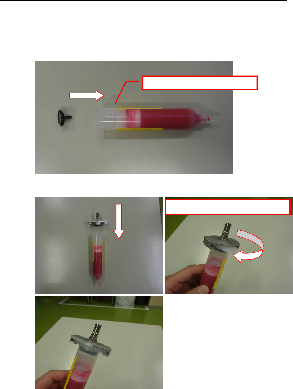
■ Installing the magnet set for remaining amount detection
■ Installing the syringe holder
Insert the magnet into the plunger.
Rotate to align with the syringe's flange orientation.
3 Mechanical Section
3-17
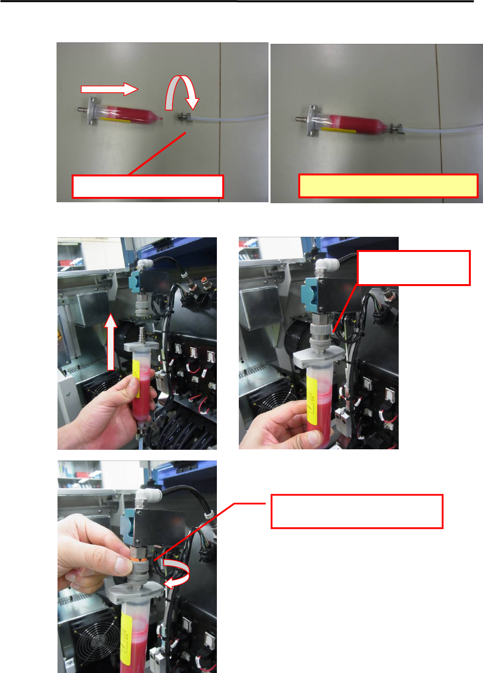
■ Connecting the tube joint and syringe
■ Connecting to the valve
Screw the tube joint in clockwise.
Use care to avoid stripping the threads.
Insert until a latching
sound (click) is heard.
Rotate the lug in the clockwise direction
to lock it.