c900795.R02_EN.pdf - 第43页
3 Mechanical Section 3-5 Assembling STD. DP HEAD The below is an assembly drawing and part list of STD. DP Head. Part List No. PART NO. PART NAME Q’T Y No. PART NO. PART NAME Q’T Y 1 LE6-M5F5N-00x PIPE, FITTING 1 5 LE6-M…

3 Mechanical Section
3-4
Inspection for Head/Nozzle Clogging and Solenoid Valve
Breakdown
The following inspection must be carried out approximately once a week.
■ Inspection of Solenoid Valve
The switching valve of the solenoid valve may catch foreign matter causing air leakage. Air leakage will
turn the suction ON even if it is turned OFF.
As a result, the suction cannot be turned OFF after a component is mounted, and components may be
returned instead of being mounted on the PCB.
● Inspecting by selecting [Manual] – [Meas. Air pressure]
①Checking the maximum air pressure
Turn ON the suction and press the head tip with fingers to check the air pressure. The air pressure is
satisfactory if it is “600” or higher.
②Checking the head for clogging
With no nozzles placed in the head, turn ON the suction to check the air pressure. Typical air pressure is
approx. “70”. An error will occur if the air pressure is “180” or higher during vacuum check performed
after nozzle replacement.
③Checking the nozzle for clogging
With nozzles placed in the head, turn ON the suction to check the air pressure. “Nozzle clog criteria” has
been set for each nozzle. The air pressure must be below the criteria. If it is not, the nozzle will be
considered to be clogged and an error will occur.
④Checking the solenoid valve for switching failure
Turn OFF the suction and check for change in the air pressure.
- Press the head/nozzle tip with fingers and check for change in the air pressure.
- Turn ON and OFF the suction a few times and check for change in the air pressure.
If the air pressure changes even though the suction is OFF, air is probably leaking from the suction solenoid
valve.
NOTE: Do not disassemble the solenoid valve. Manufacturer’s guarantee will be ineffective if the solenoid valve is
disassembled.
Part Name
Part No. Remark
VALVE LE6-M71A2-B0X Supply Valve
VALVE LE6-M71A2-C0X Breaking Valve
NOTE: For official inspection, use of a digital vacuum meter is necessary to check accuracy of the displayed air
pressure value.
Part Name
Part No. Remark
MANOMETER ASSY. LC1-M89A5-00X Vacuum Gauge Set
3 Mechanical Section
3-5
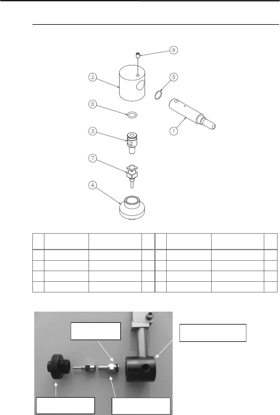
Assembling STD. DP HEAD
The below is an assembly drawing and part list of STD. DP Head.
Part List
No. PART NO. PART NAME
Q’T
Y
No. PART NO. PART NAME
Q’T
Y
1 LE6-M5F5N-00x PIPE, FITTING 1 5 LE6-M5FBV-00x O-RING 1
2 LE6-M5F65-00x BRACKET NOZZLE 1 6 LE6-M5FF7-10x SET, SCREW 1
3 LE6-M5F69-00x ADAPTER 1 7 LG7-M740S-xxx SINGLE NOZZLE SEL. 2
4 LE6-M5F6A-00x LOCK, ADAPTER 1 8 90200-02J050 O-RING 1
① The dispensing head is composed of the following parts.
BRACKET NOZZLE
LE6-M5F65-00x
ADAPTER
LE6-M5F69-00x
LOCK ADAPTER
LE6-M5F6A-00x
O-RING
90200-02J050
3 Mechanical Section
3-6
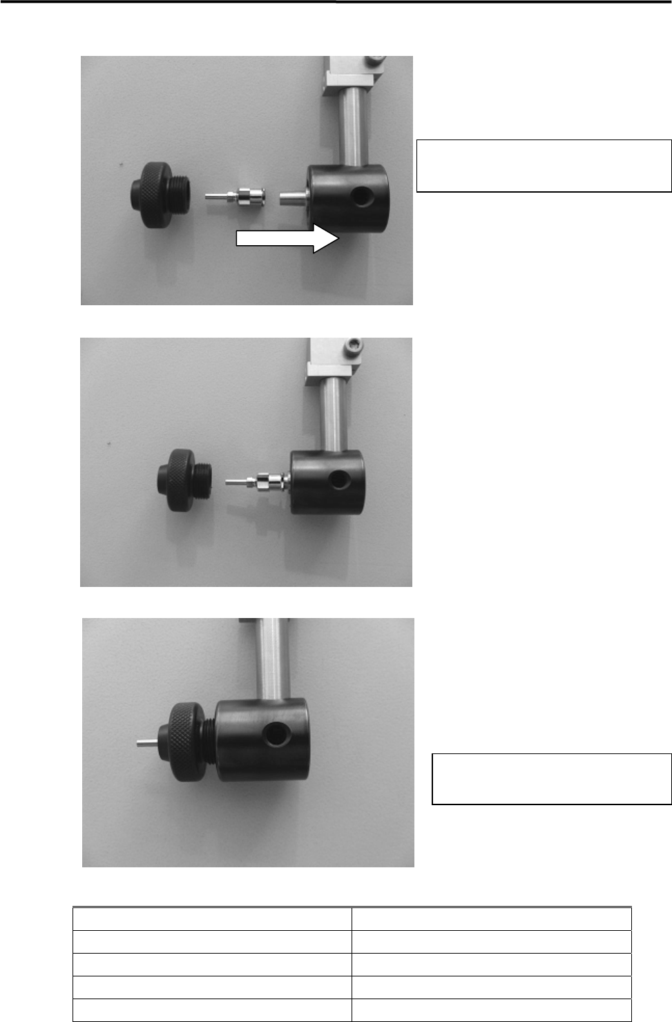
② Insert ADAPTER to BRACET NOZZLE
③ Set NOZZLE on ADAPTOR
④ Assemble LOCK ADAPTER on BRACKET NOZZLE
Reference; Dispensing Nozzle List
PART NAME PART NAME
LG7-M740S-10x NOZZLE, SINGLE (15G)
LG7-M740S-30x NOZZLE, SINGLE (19G)
LG7-M740S-50x NOZZLE, SINGLE (22G)
Lg7-M740S-70x NOZZLE, SINGLE (25G)
Make sure that O-RING has been put on
ADAPTOR before inserting ADAPTOR.
Tighten LOCK ADAPTER just enough
not to be loosened.