4OM-1431-006_w.pdf - 第126页
1-67 0802-002 5. Consumables and Important Servicing Parts 5. Consumables and Important Servicing Parts 5.1 List of Consumables Listed below are the parts that may be consumed within one year . Consult our marketing depa…
1-66
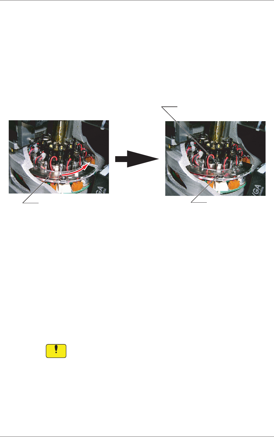
(5) Shake it in the rotational direction and conrm that the it does not
rotate. After that, pull out the lter replacement jig carefully so as not to
pull up the inserted lter together and stay aoat.
(6) Note the following and slide the lter fastener to the right to lock the
lter holder.
•
Conrm
thatthelterfasteningclaw
islocated
attheupper
centerofthelterholder.
•
Conrmthattheballplungerislocked.
Ball Plunger Locked
Slide the filter fastener to the right.
Filter Unlocked Filter Locked
Locking Position of Filter
Fastening Claw
Filter Unlocked Filter Locked
Fig.
4A64
When the lter fastening claw cannot be locked after being slid because
it interferes with the sideface of the lter holder, it can be assumed that
a foreign substance exists in the hole or the lter holder is not inserted
sufciently far into the hole.
Check the lter holder that has interfered with the sideface.
If a foreign
substance exists in the hole, clean the lter holder to remove
the substance.
After the cleaning is completed and no foreign substance is found in the
hole, starting with Step (4).
Notice
Unlessthelterholderissetcorrectlyinplace,apickuperrorwill
occurorthelterwillcomeoffandcauseaninterferencewitha
head.
The head may also be damaged.
4.7 Replacement Procedure of Vacuum Filters
0709-001
1-67
0802-002
5. Consumables and Important Servicing Parts
5. Consumables and Important Servicing Parts
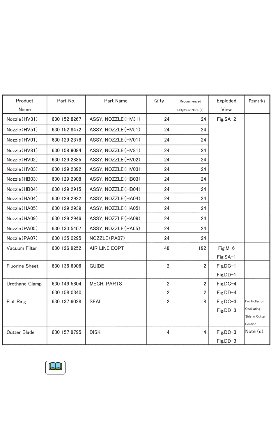
5.1 List of Consumables
Listed below are the parts that may be consumed within one year.
Consult our marketing department or sales agency whenever you need to
purchase these parts.
Table 4A14
Note
(a) The numbers entitled "Recommended Q'ty/Year" indicate the
referential values.
(b) Refer to "3. Maintenance Spots" and "4. Maintenance Method" for the
replacement procedures of these parts.
(c) Replacement of the cutter blades involves some danger. Consult our
service personnel for detailed information.

1-68
0802-002
5.2 List of Important Servicing Parts
5.2 List of Important Servicing Parts
Listed below are the parts for which maintenance work is required in several
years. The list below is provided for your reference.
Note
Since replacement work of important service parts requires highly
sophisticated technique, consult our service personnel for details
Table 4A15
Block
Name
Product Name Part No. Part Name Q'ty
Recommended
Years
Note (a)
Exploded
View
Remarks
Head
Section
Solenoid Valve 630 141 4539 ACCESSORY,
SV
24 3 Fig.M-6
Nozzle Shaft
Assembly Nozzle
Shaft Diffusion Plate
(Small)
630 146 4565
630 127 3235
630 127 7660
ASSY,
GUIDE, LINEAR
GUIDE, LINEAR
DISK
24
Sets
(1)
(1)
――― Fig.M-6
Hexagon Socket
Head Bolts M2×6
630 008 3057 BOLT, HEX-SCT 48 ――― Fig.M-6
For Nozzle Shaft
Attachment
Note (b)
O Ring for Nozzle
Shaft
SO-010-19
630 125 6382 SEAL 48 2 Fig.M-6
O Ring for Nozzle
Shaft
SO-010-21
630 055 3253 SEAL 24 2 Fig.M-6
Spring for Nozzle
Shaft
630 125 1417 SPRING, COMP 24 ――― Fig.M-6
Packing for Nozzle
DYR-3
630 127 3792 SEAL 48 2 Fig.M-6
O Ring for Filter
SO-006-12
630 076 5090 SEAL 72 2 Fig.M-6
Linear Measure
Sensor
Linear Measure
Sensor Light Emitter
630 157 4943
630 161 8654
SENSOR, PELEC
SENSOR, PELEC
2Sets ――― Fig.M-6
Outer Diffusion Plate 630 128 2763 DISK 2 ――― Fig.M-6
Inner Diffusion Plate 630 127 7677 DISK 2 ――― Fig.M-6
Hexagon Socket
Head Bolt M1.6 × 4
630 129 7064 BOLT, HEX-SCT 14 ――― Fig.M-6
For Diffusion Plate
Attachment
Note (b)
Top Block 630 145 0018 BLOCK 24 ――― Fig.M-6
Cam Follower (φ2.5) 630 125 0328 CAMFOLLOWER 24 ――― Fig.M-6
Hexagon Socket
Head Bolt M1.6 × 3
630 129 7057 BOLT, HEX-SCT 48 ――― Fig.M-6
For Top Block
Attachment
Note (b)
Sensor PM-L24 630 080 5369 SENSOR,
PHOTO
2 3 Fig.M-4
Sensor PM-F24 630 125 0878 SENSOR,
PHOTO
10 3 Fig.M-2,3
Slip Ring 630 125 0441 COUPLING 2 2 Fig.M-5