00193407-02 HWWS SIPLACE Machine Accuracy EN.pdf - 第118页
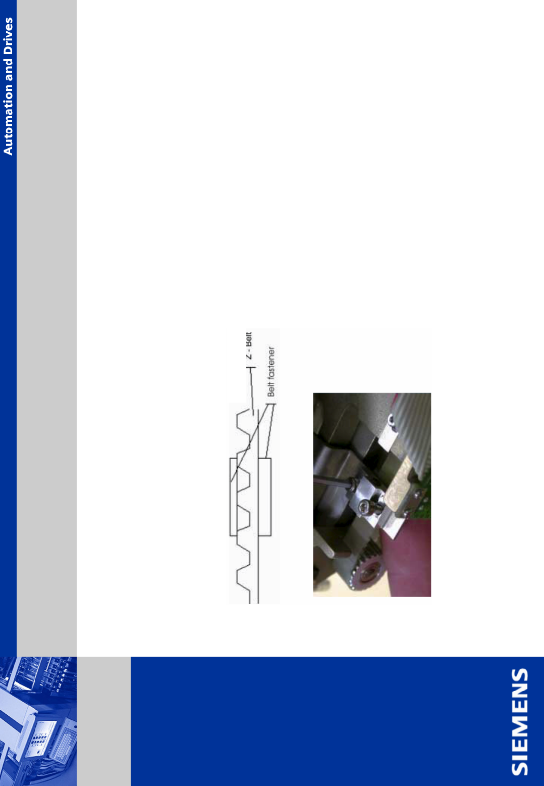
. Seite 18 © Siemens AG . . Änderungen vorbehalten SIPLACE Placement Systems ¾ tighten the screws of belt fastener. ¾ mount the belt fastener in the sa me position on the be lt as before. It is visible on the crush marks…
. Seite 17
© Siemens AG . . Änderungen vorbehalten
SIPLACE
Placement Systems
¾ take out the raceway gap gauge.
¾ use either 0.01 mm, 0.02 mm or 0.03 mm feeler gauge to the right and left of the Z-axis
to center it in the raceway gap.
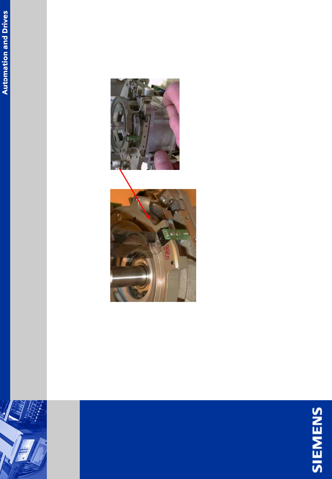
¾ move the z-axis up and down and check if the z-axis is centrically placed.
¾ tighten the screws of the z-axis driving plate.
¾ remove the feeler gauges.
¾ move the z-axis up and down with a slightly pressure to the left and to the right. You should
not feel any ‘scratching movement’, otherwise the z-axis has to be centered again.
¾ put the forced-air hoses back on.
Assembly Z-Axis (continuing)
. Seite 18
© Siemens AG . . Änderungen vorbehalten
SIPLACE
Placement Systems
¾ tighten the screws of belt fastener.
¾ mount the belt fastener in the same position on the belt as before. It is visible on the crush
marks.
¾ place the belt fastener on the toothed belt such in a way that the edges are on the teeth or on
the space.
¾ the single parts of belt fastener can be aligned with a 10 mm spanner.
Z-belt belt fastener
Assembly Z-Axis (continuing)
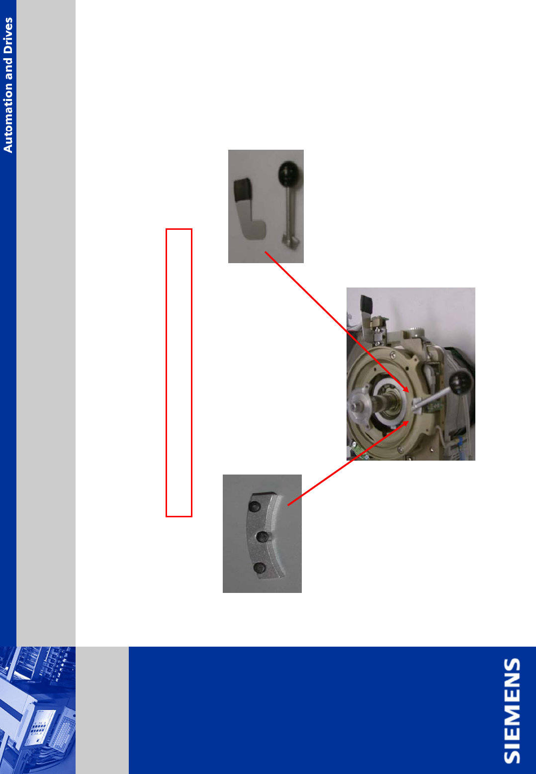
Check belt tension using belt tension meter:
C&P DLM head: 280 +- 10 Hz
. Seite 19
© Siemens AG . . Änderungen vorbehalten
SIPLACE
Placement Systems
C&P M 8000, M 10 000: z-axis gauge shown below must be used
alternative
Attention: only C&P M 8000, M 10000 head
Assembly Z-Axis only M 8000, M 10000