00193407-02 HWWS SIPLACE Machine Accuracy EN.pdf - 第121页
. Seite 21 © Siemens AG . . Änderungen vorbehalten SIPLACE Placement Systems order number 00326164-01 don’t mix it up with the gauge for adjusting the zero poi nt correction gauge star axis C&P DLM head : z-axis gaug…
. Seite 20
© Siemens AG . . Änderungen vorbehalten
SIPLACE
Placement Systems
C&P M 8000 / M 10000
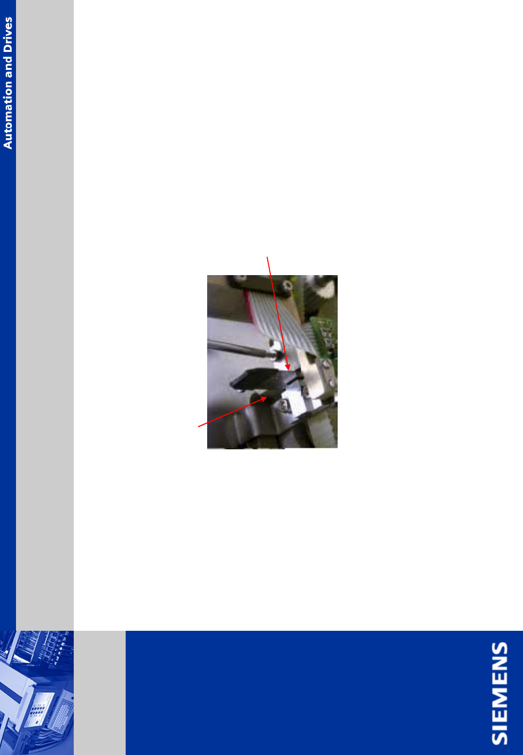
¾ loosen and remove the hexagon socket head screw (1.5 mm allen wrench) of
z-axis upper stop.
¾ place a 0.3 mm feeler gauge on the upper stop.
¾ push the z-axis stop in the direction of the belt fastener and tighten the screw of the
z-axis upper stop.
¾ remove the feeler gauge and the gauge for z-axis upper stop.
¾ check belt tension using belt tension meter:
belt tension: C&P head: M 8000 / M 10000 head: 190 +- 10 Hz
upper stop z-axis
Assembly Z-Axis only M 8000, M 10000
. Seite 21
© Siemens AG . . Änderungen vorbehalten
SIPLACE
Placement Systems
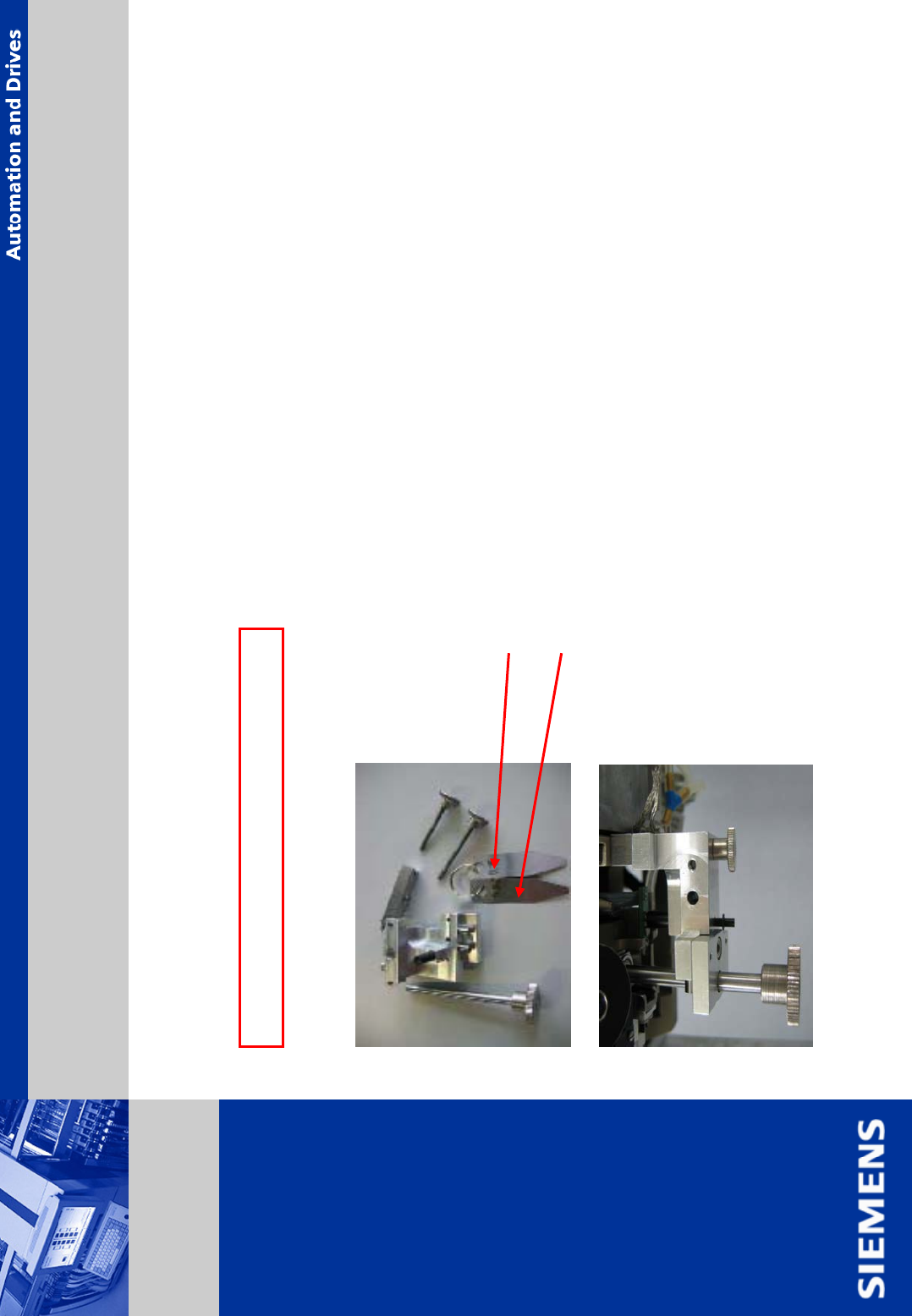
order number 00326164-01
don’t mix it up with the gauge for adjusting the zero point correction
gauge star axis
C&P DLM head: z-axis gauge shown below must be used
see Technical Info 10C06014
Attention: only for C&P DLM head
Assembly Z-Axis only DLM Head
0,15mm
0,05mm
. Seite 22
© Siemens AG . . Änderungen vorbehalten
SIPLACE
Placement Systems
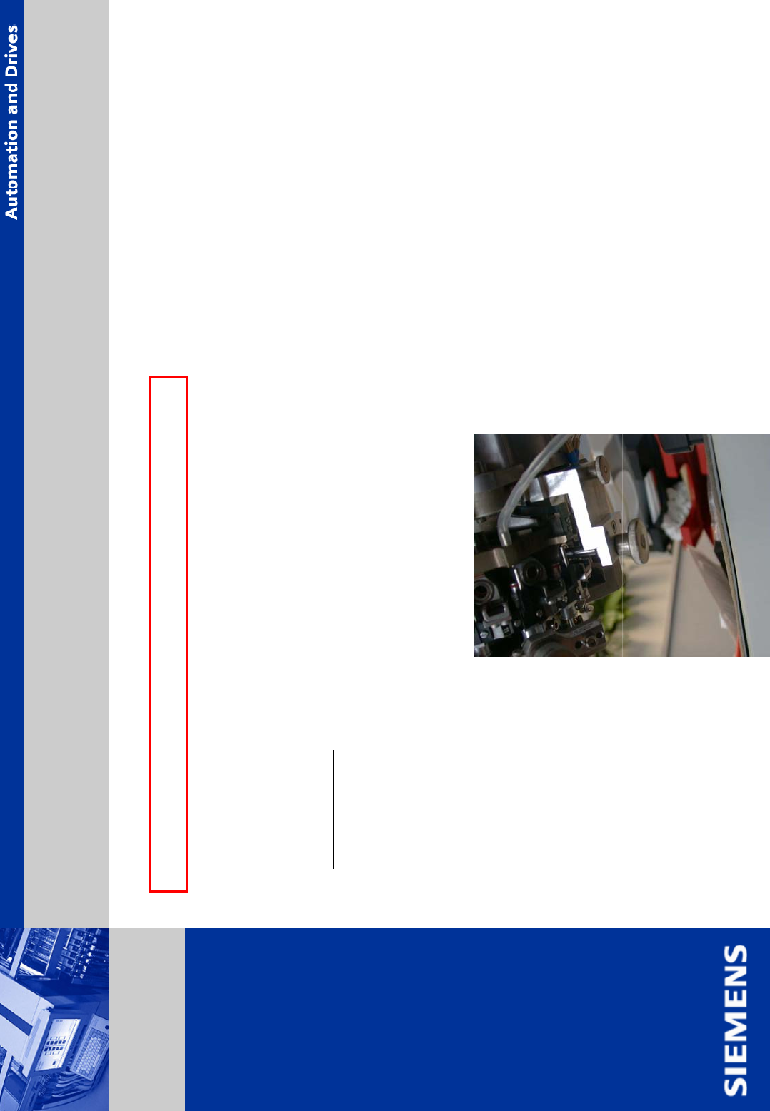
¾ mount the star in the marked position. To do so, pull out the 3 segments, located below the
fastening tools.
¾ put the star carefully back onto the motor shaft.
ATTENTION:
don’t squeeze the vacuum tubes and ensure the segment bearings run
correctly in the raceway.
¾ insert the 3 screws (DIN 912 M3x8mm) for the star, do not tight them yet.
¾ mount the star zero point correction tool.
Continuing all C&P head M 8000 / M10000, DLM head
Assembly Z-Axis (continuing)