00193407-02 HWWS SIPLACE Machine Accuracy EN.pdf - 第123页
. Seite 23 © Siemens AG . . Änderungen vorbehalten SIPLACE Placement Systems Adjusting the star with respect to the star’s magneti c neutral position The aim of adjusting the star is to ensure that the vertical axis of s…
. Seite 22
© Siemens AG . . Änderungen vorbehalten
SIPLACE
Placement Systems
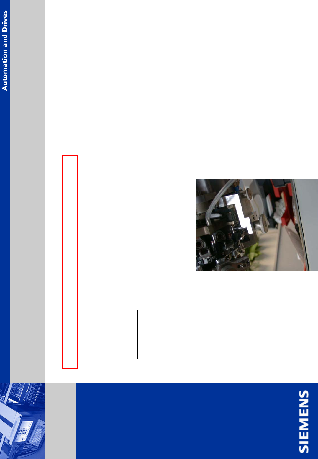
¾ mount the star in the marked position. To do so, pull out the 3 segments, located below the
fastening tools.
¾ put the star carefully back onto the motor shaft.
ATTENTION:
don’t squeeze the vacuum tubes and ensure the segment bearings run
correctly in the raceway.
¾ insert the 3 screws (DIN 912 M3x8mm) for the star, do not tight them yet.
¾ mount the star zero point correction tool.
Continuing all C&P head M 8000 / M10000, DLM head
Assembly Z-Axis (continuing)

. Seite 23
© Siemens AG . . Änderungen vorbehalten
SIPLACE
Placement Systems
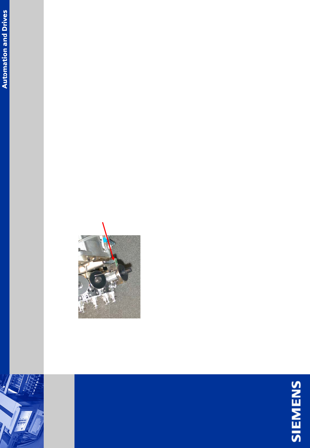
Adjusting the star with respect to the star’s magnetic neutral position
The aim of adjusting the star is to ensure that the vertical axis of segment no. 1 is aligned with
the magnetic neutral position of the star stepper motor.
¾ to do this, insert the star zero point correction tool in segment 1 and tighten it.
¾ pull off the motor power plug of the star motor from socket X5 on the intermediate distribution
board and connect the motor power to the power supply.
¾ connect the power supply unit to the main power
ATTENTION: maximum operation time should not
exceed 5 minutes
¾ tighten the M 3x8 hexagon socket head screws.
¾ remove the gauge pin.
¾ insert the gauge pin again into the gauge and into the segment hole, until it reaches the stop,
then check:
- that the gauge pin can be inserted easily
- that the star does not move from its current position.
¾ disconnect the power supply from the power source.
¾ repeat the adjustment procedure if the gauge pin does not slide easily into the hole.
Adjustments on Revolving Head
. Seite 24
© Siemens AG . . Änderungen vorbehalten
SIPLACE
Placement Systems
¾ check the bottom light sensor adjustment (1,0 mm).
¾ check the distance between reader head dp-axis and segment sleeve (1.4 - 1.6 mm)
¾ replace the O-rings correctly. move the star a half cycle
¾ check the valve drive adjustment (0,2 mm).
¾ connect the cables to the head board
¾ push compressed air hose back into position.
¾ switch on the placement station, adjust the star zero point correction and perform a C&P head
calibration
.
Adjustments on Revolving Head