00193407-02 HWWS SIPLACE Machine Accuracy EN.pdf - 第54页
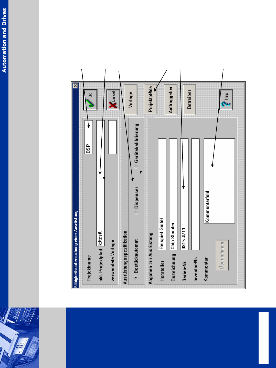
© Siemens AG . . Änderungen vorbehalten SIPLACE Placement Systems project name change path path machine type equipment number comment Basic Data CM Controller – Measuring Project

© Siemens AG . . Änderungen vorbehalten
SIPLACE
Placement Systems
¾ MFU contains 1 measurement as a minimum.
¾ the number of placed components is depending on the head type.
Standard realization
¾ RV12 C&P head: 144 pieces of components (0201, 0402, 0603, ….. ceramic pads)
¾ RV6 C&P head: 48 pieces glass components (TQFP 92)
¾ P&P head: 48 pieces glass components (TQFP 92)
¾ RV 20 head 144 pieces of components (0201, 0402, 0603, ….. ceramic pads
(can be customized to max. 480 components)
in certain circumstances and on customer tailored measurements, the number of
components and number of measurements can be changed (ask regional SCC for more
info).
The aim is, to receive a protocol for each individual machine and each head type.
This is the proof for placement accuracy within the predetermined limit which is frequently
determined by the machine manufacturer, e.g. Siplace 80S 90µm / 4Sigma).
If required, the customer can use alternative specification values for the measurements.
he values must be comparable (ask regional SCC for more info)
Machine Capability Analysis (MCA)
© Siemens AG . . Änderungen vorbehalten
SIPLACE
Placement Systems
project name
change path
path
machine type
equipment number
comment
Basic Data
CM Controller – Measuring Project
© Siemens AG . . Änderungen vorbehalten
SIPLACE
Placement Systems
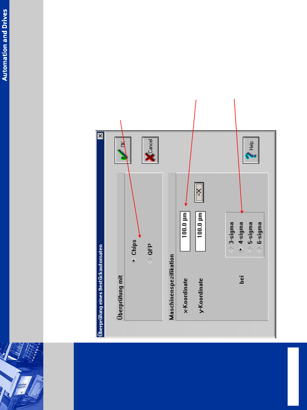
Specification
specification limit
dummy type
(depends on machine tape)
¾ max.4,5mm size for 12 nozzle
head (2 contacts)
¾ (glass dummies for pick &
place head and 6 nozzle head
sigma
CM Controller – Measuring Project