SM411F_Service Manual.pdf - 第157页
Electric Device 3.3.3. VME Part Board Assembly PC R A CK 구성 PC 부 BOA RD 순 서 NEX TEY E IMA GE GAR BBE R #1, #2 PCI IO BOA RD SBC BOA RD VME RAC K부 BOA RD 순 서 M31 00 BOA RD CAN MAS TER BOA RD VIS ION IF BOA RD VME IO BOA R…
Electric Device
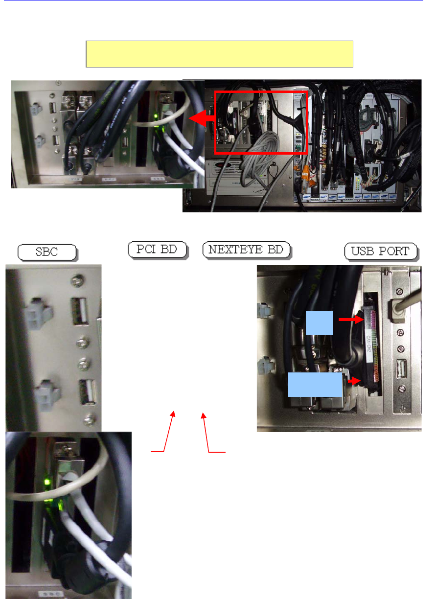
CH1
CH2
LAN
Monitor
The Connection Diagram of the PC Wiring Connector
Electric Device
3.3.3. VME Part Board Assembly
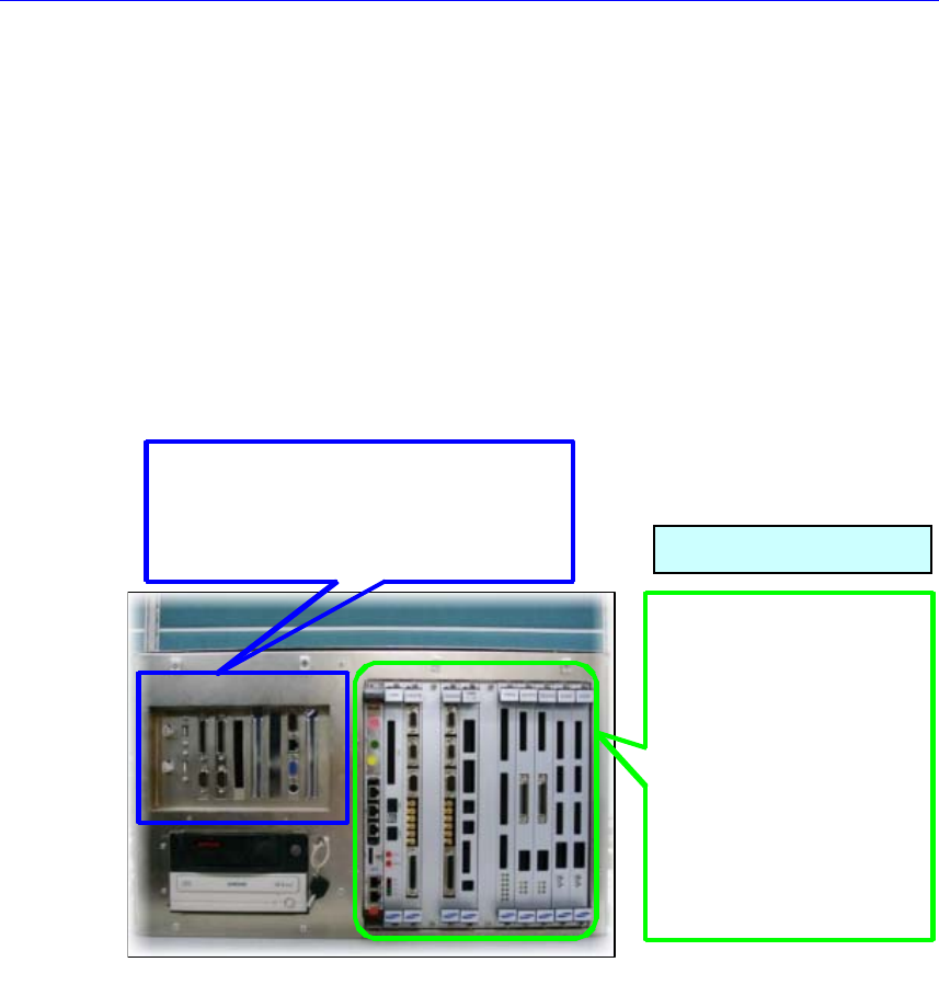
PC RACK 구성
PC 부 BOARD 순서
NEXTEYE IMAGE GARBBER #1,#2
PCI IO BOARD
SBC BOARD
VME RACK부 BOARD 순서
M3100 BOARD
CAN MASTER BOARD
VISION IF BOARD
VME IO BOARD
TWIN SERVO BOARD
X7043 SEDES BOARD
X7043 STEP CON. BOARD
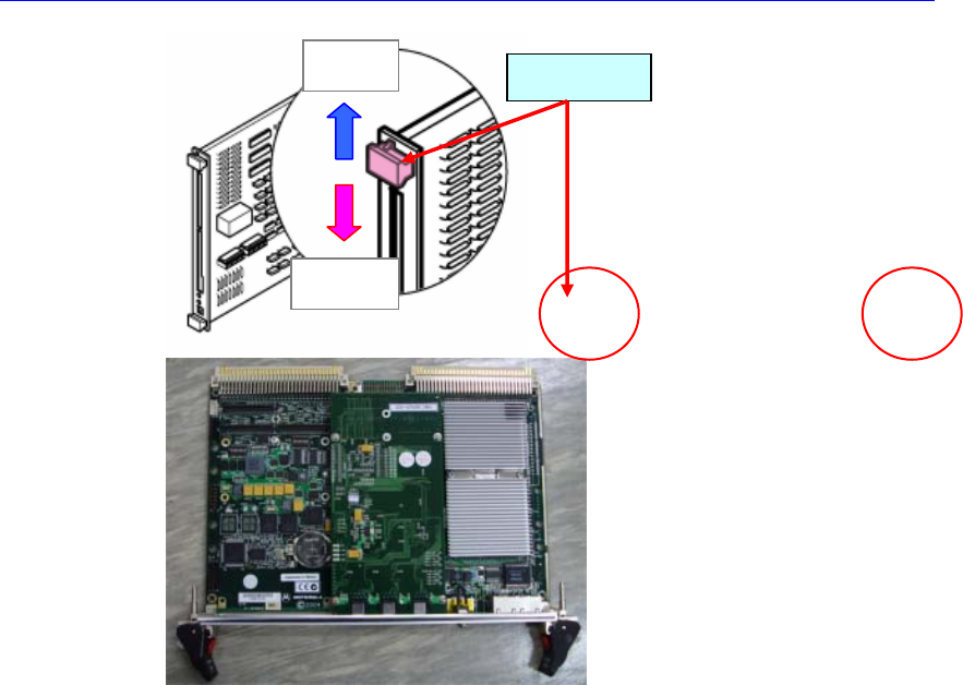
3.3.3.1. VME board assembly replacement procedure
1. Perform steps from No. 1 to No. 3 of the “3.3.2.1 PC board assembly
replacement procedure (page 3-1)”
2. Disconnect the cable connected to the board to be replaced.
3. Remove the fixing bolts (2 sets) of the board to be replaced by using a screw
driver.
MVME3100 BOARD
VME Board Assembly
PC RACK CONFIGURATION
PC BOARD LIST
VME RACK BOARD LIST
Electric Device
4. Perform steps from No. 5 to No. 7 of the “3.3.2.1 PC board assembly
replacement procedure (page 3-1)”
Open
Fixing
Eject Lever