SM411F_Service Manual.pdf - 第77页
1.2.10.1. Fix Camera Scale Calibration The fix camera calibration must be perfo rmed before performing fiducial camera offset calibration. First, teach the fiducial mark on the upp er surface of the fix camera and perfor…
1.2.10. Head & Camera Calibration
Perform the camera calibration function. The calibration sequence and tools
necessary for calibration are as follows.
- Fiducial Camera Offset Calibration (Calibration Tool)
- Head Z & R Offset Calibration (CN040 Nozzle)
- Light Mapping (LightFly Nozzle)
- Head Offset Calibration
- Fly Camera Scale & Rotation Calibration
- Fly Camera Offset Calibration
- Fly To Fix Offset Calibration
- R-Axis Offset Calibration
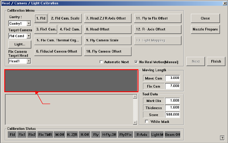
Figure 1-8. “Head/ Camera/ Light Calibration” dialogbox
<Calibration Menu> Group
Select an item to be calibrated. If you click the button of a specific item, the
description on the works to be performed are displayed in the message box in
order. Follow the instructions to complete the calibration.
<Gantry> combo box
Select the Gantry for performing Calibration
<Target Camera> combo box
Select the camera to set light value.
<Light…> button
Set the light value for the selected camera.
Messa
g
e box
1.2.10.1. Fix Camera Scale Calibration
The fix camera calibration must be performed before performing fiducial camera
offset calibration.
First, teach the fiducial mark on the upper surface of the fix camera and perform
calibration of the fix camera scale using the CNT20 nozzle.
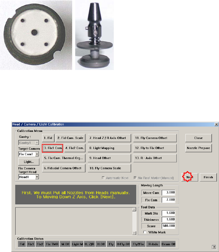
<3. Fix 1 Camera> button
This calibration is performed to calibrate the Scale (um/pixel), Rotation (deg)
and Position (mm) of the fix-camera.
In order to perform this calibration first, the R-Offset Calibration must be
performed in advance and the calibration-nozzle must be used. Use Hole #1 as
the ANC hole exclusively used for the calibration-nozzle.
The following is the procedure to calibrate the Fix Camera Scale;
1. If the <3. Fix1 Camera> button is clicked, the message “First, We must Put
all Nozzles From Heads on Manually. To Move down Z Axis, Click
[Next]” appears in the message box. Click the <Next> button to move
down the Z axis of the head in order to manually move all nozzles inserted
in the nozzle holder of the head.
2. Then, after the head assembly moves to the designated position, move all Z
axes down. At this time, remove all inserted nozzles manually
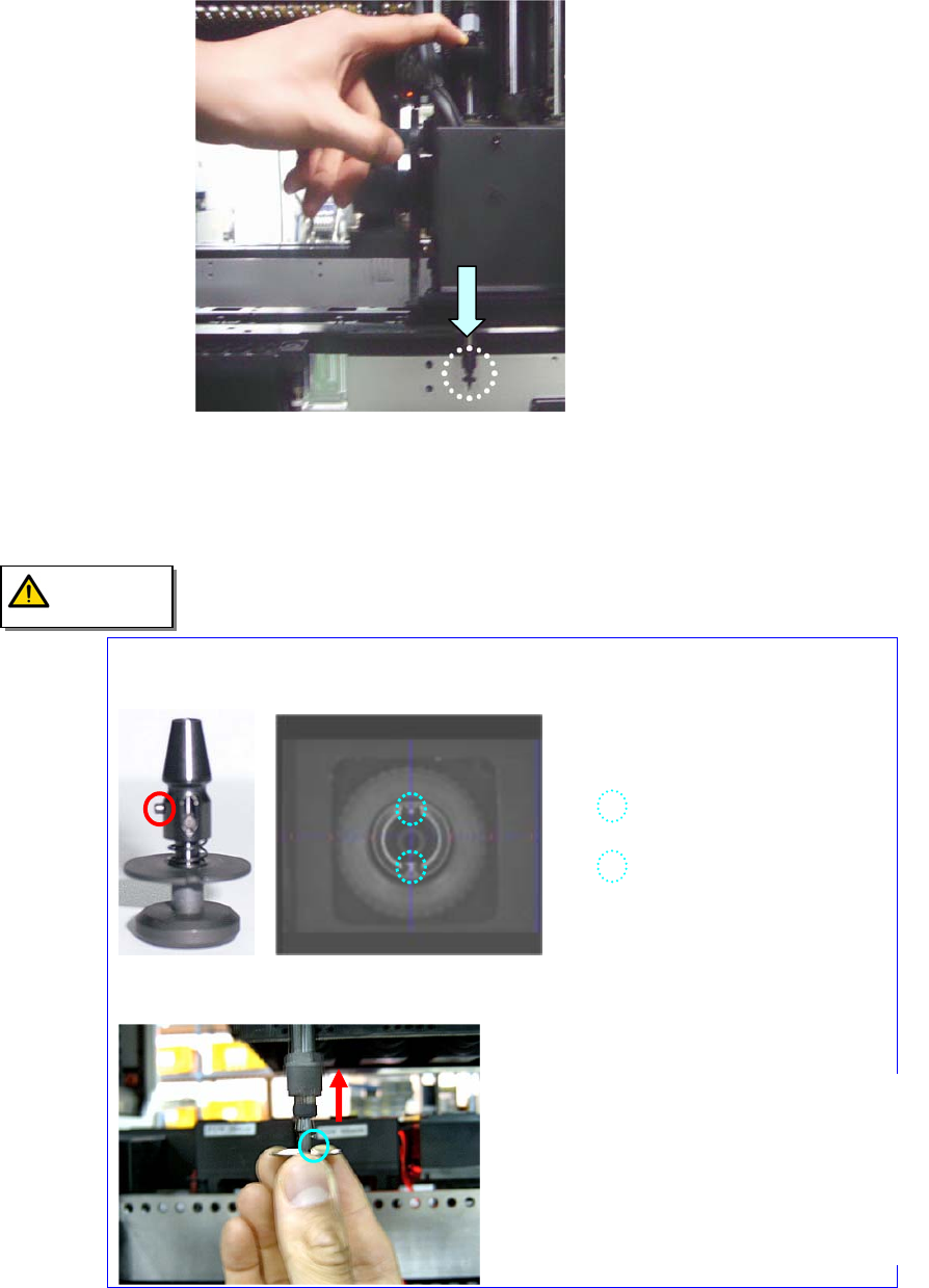
3. “Then the message “Next Attach the Calibration Tool to Head 1. Click
[Next] for Moving Down Head. After Moving, Attach the Tool to head
Manually” appears. Click the <Next> button after inserting the CNT20
nozzle at nozzle holder of Head #1 manually.
Cautions to be taken when inserting the CNT20 nozzle.
Insert the CNT20 nozzle by referring to the following figure.
<Direction Setup Pin of CNT20 nozzle > <Direction Setup Groove of Nozzle
Holder >
4. The message “Move To Center Position of [Fix1] Camera. To Move, Click
[Next]” appears in the message window. Click the <Next> button to move
The CNT20 nozzle must be inserted in
the nozzle-holder so that the direction-
setup pin of the CNT20 nozzle is suitable
for the direction-setup groove of nozzle-
holder. Otherwise, an error may occur.
Caution