SM411F_Service Manual.pdf - 第61页
1.2.5.1. Procedure Conveyor Calibration method is as follows. 1. “Click the <Home All> button in the “Conveyor Calibration” dialog box. 2. Select the station to be calibrated from the <S tations> combo box. 3…
Applies the changed value and closes the dialog box.
<Shuttle Index Pos> Group
Provides the function that can adjust the outlet position of the exit shuttle if the
position of the fixed rail of the conveyor does not match with the discharge
position of the exit shuttle in the following equipment.
This function is enabled only when the ‘Home’ function is performed for the
conveyor rail after booting the equipment. This function is applied to the
SM411 model.
<Pos Y> Edit Box
Refers to the coordinate of the outlet position (index position) of the
current exit shuttle.
<Shuttle Move> Button
Moves the shuttle to the position inputted in the <Pos Y> edit box.
However, if the rear rail is fixed, it moves the shuttle to the position less
the width of the current rail.
<Shuttle Get> Button
Sets the current shuttle position as the coordinate of the machine. Move
the exit shuttle using the jog function of the teaching box to match it with
the fixed rail of the next machine, and click this button to input the
coordinate of the shuttle index position in the <Pos Y> edit box.
In the case of the equipment with fixed rear rail, adjust the conveyor width
so that it becomes identical to the conveyor width of the following
equipment, and move the exit shuttle to the position that allows PCB
transfer between two equipments using the jog function and then click this
button to save the coordinate of the shuttle index position. At this time,
input the value obtained by adding the width of the current rail to the
current position in the <Pos Y> edit box.
[Setup Sequence of the Jog Function of the Teaching Box]
Jog Æ Conveyor Æ Station Æ Shuttle Axis
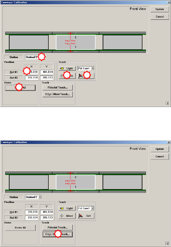
1.2.5.1. Procedure
Conveyor Calibration method is as follows.
1. “Click the <Home All> button in the “Conveyor Calibration” dialog box.
2. Select the station to be calibrated from the <Stations> combo box.
3. Click the <Fiducial Teach…> button to teach the fiducial marks of the selected
station accurately and click the <Tuning> button to scan the position accurately.
4. Click the <OK> button to update the information on the fiducial mark position.
5. Click the <Edge Offset Teach…> button
6. Select the <Edge Offset> edit box corresponding to the “Ref. #1” and click the
<Move Cam> button.
2
1
3
4
5
1
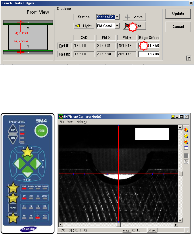
7. Then the downward camera (fiducial camera) moves to the corresponding
position of the fiducial mark. Select XY by pressing the ‘AXIS’ button using
the teach box to make the backup table rise and make the edge of the transport
rail frame correspond with the horizontal line of the cross lines in the vision.
Then select the jog by pressing the ‘MODE’ button, and slowly move by
pressing the Y(+) direction move button.
8. When matched, press the ‘Enter’ button in the teaching box.
9. Select the corresponding <Edge Offset> edit box in ‘Ref. #2’ and click the
<Move Cam> button.
10. Perform teaching on ‘Ref. #2’ in the same way as teaching on ‘Ref. #1’.
1
2
F2_Ref#