SM411F_Service Manual.pdf - 第166页
Electric Device 3.4.3. Head Module Boar d Replacement Procedure CAN Head Illumination Board/ CAN Head I/O Board 1. Manipulate the teaching box to move the head assembly to both ends as much as possible. 2. T urn Off the …

Electric Device
CAN Head Illumination Board
CAN Head I/O Board
Vacuum Sensor Board
Camera I/O Board
3.4.2. Required Tools
Spanner
Screw driver with “+” shaped tip and screw driver with “-” shaped tip
T Wrench or Hex Wrench
Electric Device
3.4.3. Head Module Board Replacement Procedure
CAN Head Illumination Board/ CAN Head I/O Board
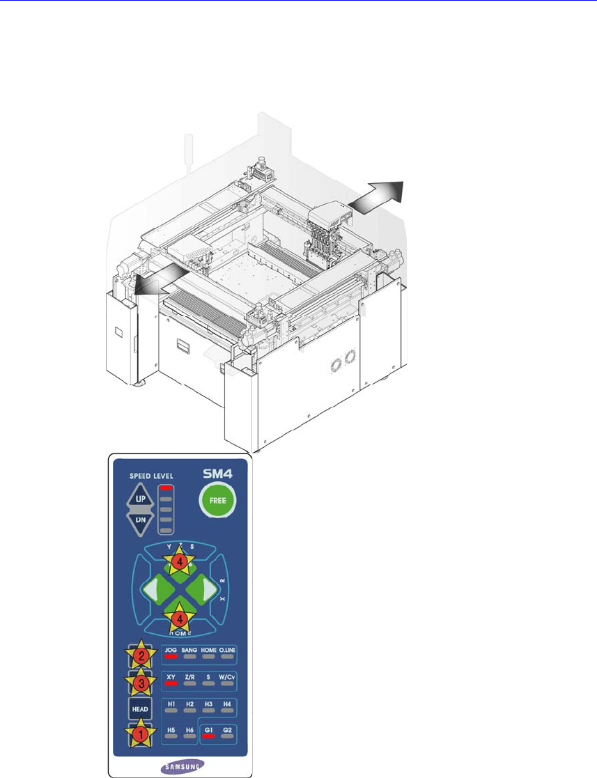
1. Manipulate the teaching box to move the head assembly to both ends as much
as possible.
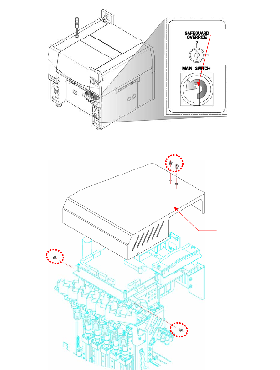
2. Turn Off the PC in normal way. Then turn off the main switch on the front side
of the machine.
Electric Device
3.
In order to disconnect the side illumination board connector at the head side, unscrew
the fixing screws (M2.5 – 4 sets) by using a wrench to remove the head top cover.
4. Disconnect the cable connected to the board to be replaced.
5. Remove the support of the board to be replaced by using the spanner.
6. The assembling is performed in the reverse order of disassembling.
7. When the ‘Head Illumination Board’ was removed, ensure to perform the fly
camera related light mapping by referring to “
오류
!
참조
원본을
찾을
수
없습니다
.
오류
!
참조
원본을
찾을
수
없습니다
. (page
오류
!
책갈피
Direction in which the
main switch is turned
off (counterclockwise)
Head Top Cover