SM411F_Service Manual.pdf - 第175页
Electric Device 3. Disconnect the connectors connected to the Feeder Control Board and Feeder Input EXT B oard. Left Feede r Base Board Output Right Feede r Base Board Output Left Feede r Base Board Input Right Feede r B…
Electric Device
3.5. Frame Board Ass’y
3.5.1. Required Tools
Spanner
Screw driver with “+” shaped tip and screw driver with “-” shaped tip
T Wrench or Hex Wrench
3.5.2. Front Upper Part
Feeder Control Board
Feeder Input EXT Board
3.5.2.1. Replacement procedure for the board on the front upper side of
machine
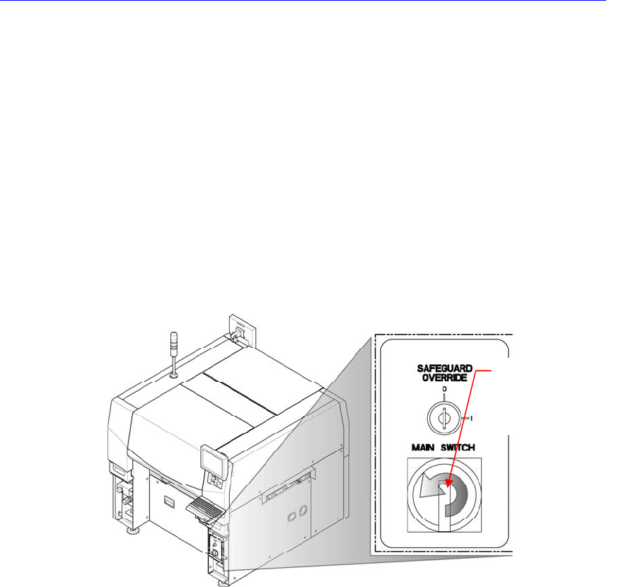
1. Turn Off the PC in normal way. Then turn off the main switch on the front side
of the machine.
2. In order to remove the feeder control board, unscrew the bolts (6 sets) of the
internal covers at the left and right sides of the machine in the following figure
by using a screw driver with a ‘+’ shaped tip and remove the covers.
Direction in which the
main switch is turned
off (counterclockwise)
Electric Device
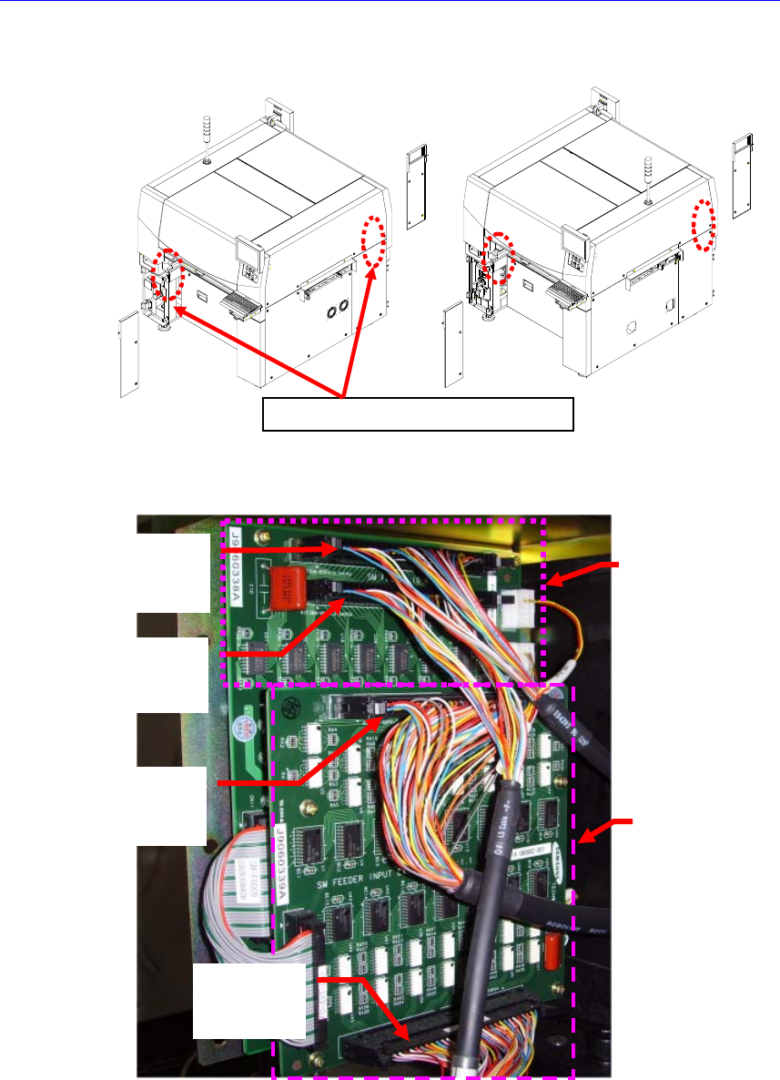
3. Disconnect the connectors connected to the Feeder Control Board and Feeder
Input EXT Board.
Left Feede
r
Base Board
Output
Right Feede
r
Base Board
Output
Left Feede
r
Base Board
Input
Right Feede
r
Base Board
Input
Feeder
Control
Board
Feeder
Input
EXT Board
Feeder Control Board Location
Electric Device
3.5.3. Front Lower Part
Axis Sensor Board (For more details, refer to “
오류
!
참조
원본을
찾을
수
없습니다
.
오류
!
참조
원본을
찾을
수
없습니다
.”
Rear Operate (KVMS) Board
3.5.3.1. Replacement procedure for the board on the front lower side of
machine
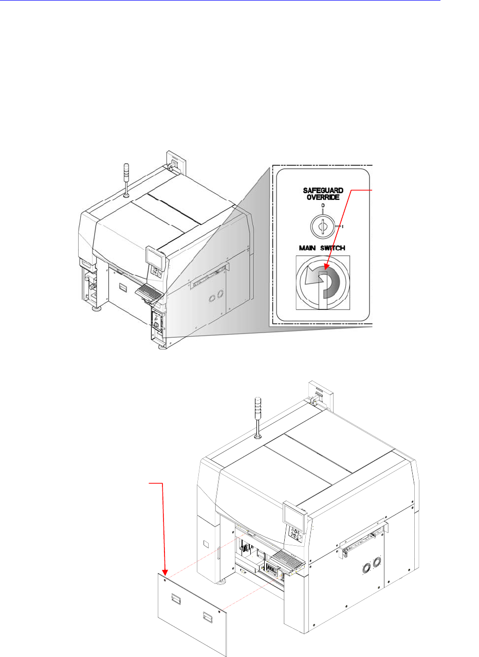
1. Turn Off the PC in normal way. Then turn off the main switch on the front side
of the machine.
2. Remove the front cover of the machine using the “+” shape tipped screw
driver.
3. Remove the connector connected to the corresponding board.
4. Unscrew the fixing screws to remove the corresponding board by using the
Direction in which the
main switch is turned
off (counterclockwise)
Cover bolt positions (2
places)