SM411F_Service Manual.pdf - 第238页
Softwar e Caution When the parts are supplied for maintenance, th e standard parameters are downloaded in the driver. Basically , the types of the parameters of the servo motor are classified as follows: Classification…
Software
Caution
For alarms related to power, turn off power and turn on
power.
3. For alarm caused by OVERLOAD, normal clear is possible in 10 seconds or more.
So, press the ‘READY’ button to supply power to the servo motor in 10 seconds or
more after pressing the ‘RESET’ button.
4. If troubles are caused by cable connection for the terminal of servomotor and
improper wiring, ensure that checking wiring is performed after motor power is off.
5. If the servomotor without mechanical problem does not drive, check if the parameter
is normal. And then if the same trouble ouccur again, replace the mortor drive.
6. If the drive of motor is not stable and acceleration/deceleration is improper, the
following checks should be performed;
Check if servomotor has mechnical problem
Check if servomotor parameter setup is normal
Check if the primary input voltage is acceptable
Check if the state of cable shield is normal.
7. The unmatched origins may be caused by serious difference between Z phase and
Home sensor or the defective axis board. So check the connections of axis board
cables.
8. The causes of noise are mainly noise, parameter, and bad connection of cable, etc.
except mechanical causes.
5.2.4. Servo Motor Driver Replacement
5.2.4.1. Required tools
Spanner
“+” shape tipped screw driver, “-” shape tipped screw driver
T Wrench or Hex Wrench
Motor Driver Data Cable (P-Motor): for Servo Motor
5.2.4.2. Driver replacement procedure
1. Press the <EMG> switch on the front side of the machine to cut off the power supply
to the motor. At this time, the power supply to the entire machine must remain turned
on or the power must be supplied to the corresponding motor driver.
2. Remove the rear cover of the machine by using a screw driver.
3. Back up the parameters saved in the previous driver by referring to “5.2.5 Parameter
Download/Upload Procedure “.
Caution
The new driver contains the standard parameters the
setups of the manufacturer. However, they may be changed
in our factory for tuning.
4. If the parameters cannot be downloaded from the existing driver, download the
distributed standard parameters.
Software
Caution
When the parts are supplied for maintenance, the standard
parameters are downloaded in the driver.
Basically, the types of the parameters of the servo motor are classified as follows:
Classification by axis: X, Y, Z (1, 3, 5 / 2, 4, 6 ), Swing, Width (C/V)
5. Turn off the power supply to the machine again.
6. Disconnect the cable connected to the driver that needs to be replaced.
7. Replace the defective motor driver.
8. The assembling is performed in the reverse order of disassembling.
9. Check if the machine works properly after turning it on.
Warning
The adjustment of the parameters for the servo motor is
not permitted in whatever case except when the driver
parameter is distributed as Service Information.
5.2.5. Parameter Download/Upload Procedure
5.2.5.1. Required tools
Spanner
“+” shape tipped screw driver, “-” shape tipped screw driver
T Wrench or Hex Wrench
Motor Driver Data Cable (P-Motor): Interface Cable
Software
Panaterm Software (panaterm version 3.70.0 )
5.2.5.2. The connection between panasonic driver and computer
1. Turn off the motor power by pressing the ‘EMG’ switch at the front operation panel
of the machine. Before pressing the ‘EMG’ switch, the power of machine or motor
driver should be on.
2. Remove the lower cover at the rear of the machine by using a screw driver.
3. Prepare note book installed with Panaterm Software. (PC in machine can be used)
4. Connect exclusive interface cable with computer (RS232 Port).
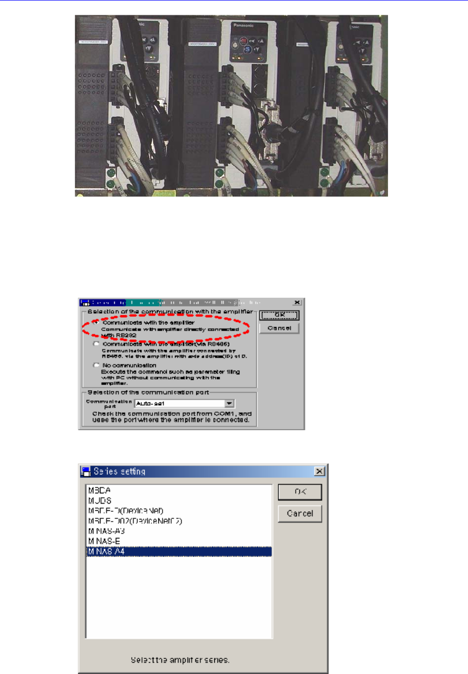
5. Connect the cable to the corresponding port of the corresponding driver.
Software
5.2.5.3. Software execution
1. Execute the panaterm software.
2. If the panaterm software is excuted, the following dialog box appears. Select
<Communicate with Amplifier directly connected with RS232> option button in the
this dialog box and click <OK> button.
3. If the ‘Series Setting’ dialog box appears, select ‘MINAS-A4’ in the list box and click
<OK> button.
4. If the massage, “Detect the Amplifier at COM#. Do you connect?”, appears, click
<Yes> button.