SM411F_Service Manual.pdf - 第23页
Main development concept– Control • Improvement of performance – Application of mini Z AMP • Maximized space use by applying Z mini AMP (Taking only 1/3 of existing mac hine’s rear surface) (6 head mi ni AMP) • Simplific…
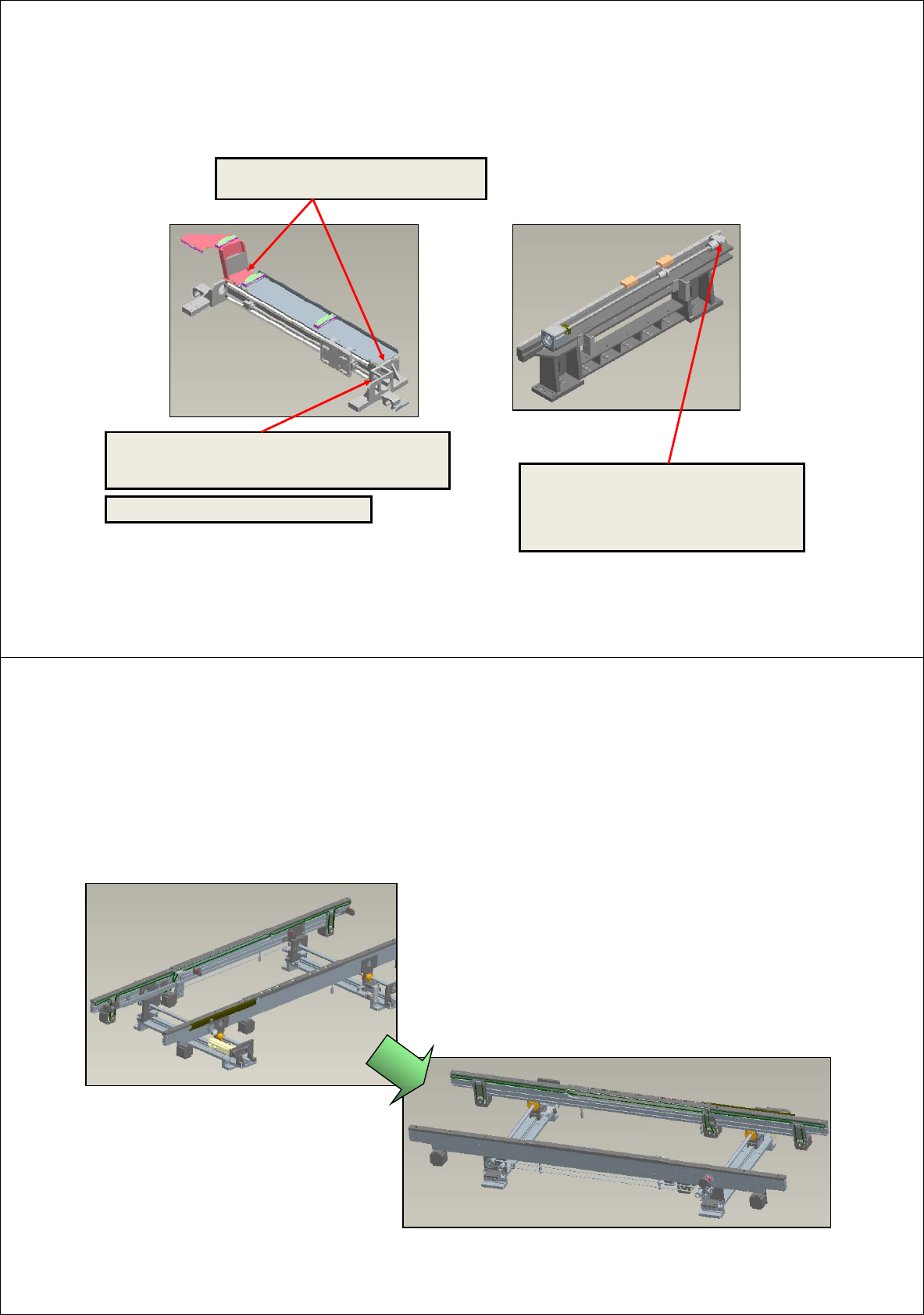
Improvement of X-Y
Improvement of assembly precision by obtaining
concentricity of X-motor and ball screw
-Assembly of X ball screw module as a unit
Improvement of assembling ability by pin
assembly of X-module
Auto paralleling arrangement of ball screw
-> Removal of assembly error in parallelism
-> Noise prevention by screw shaft bending
-> Simple attachment of screw after module
assembly and reduction of man-hour
X-frame module (As the figure above)
3
Improvement of conveyor
• Easy to change right and left (Changing time 0.5hr)
• Minimized wiring work resulted from production module (Completion of cable module)
• Applicable for all 460, 510 and large option, and minimized width related option changing time(400,460,510) 15 min.
• Completion of SM321 conveyor VOC reflection
(Improvement of hexagon bar, easy to correspond with option such as right/left change and noise of handle)
4
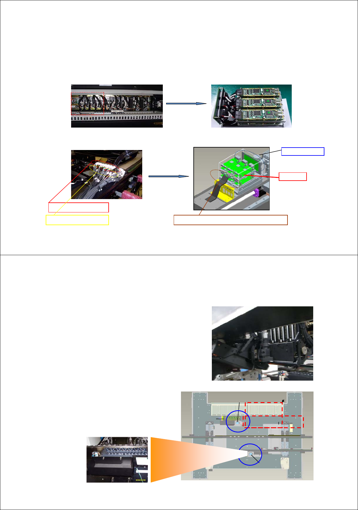
Main development concept– Control
• Improvement of performance
– Application of mini Z AMP
• Maximized space use by applying Z mini AMP
(Taking only 1/3 of existing machine’s rear surface) (6 head mini AMP)
• Simplification of wiring by applying Z mini AMP
Z1 ~ Z6 Power Cable
Z1 ~ Z6 Encoder Cable Direct connection from flat cable to mini AMP
SEDES Slave Board
①
②
③
④
⑤
⑥
Z Mini AMP
5
ANC
ANC
Stage
Camera
Stage
Camera
For Tray
Feeder
Main improvement – Vision
• Recognition of 12 head vision (SM411(F))
– 6 Head / Gantry
– Dual gantry support
6
• Recognition of 2 stage vision (SM411F only)
– 2 stage camera (Front/Rear)
– SM421 ANC
(SM411)
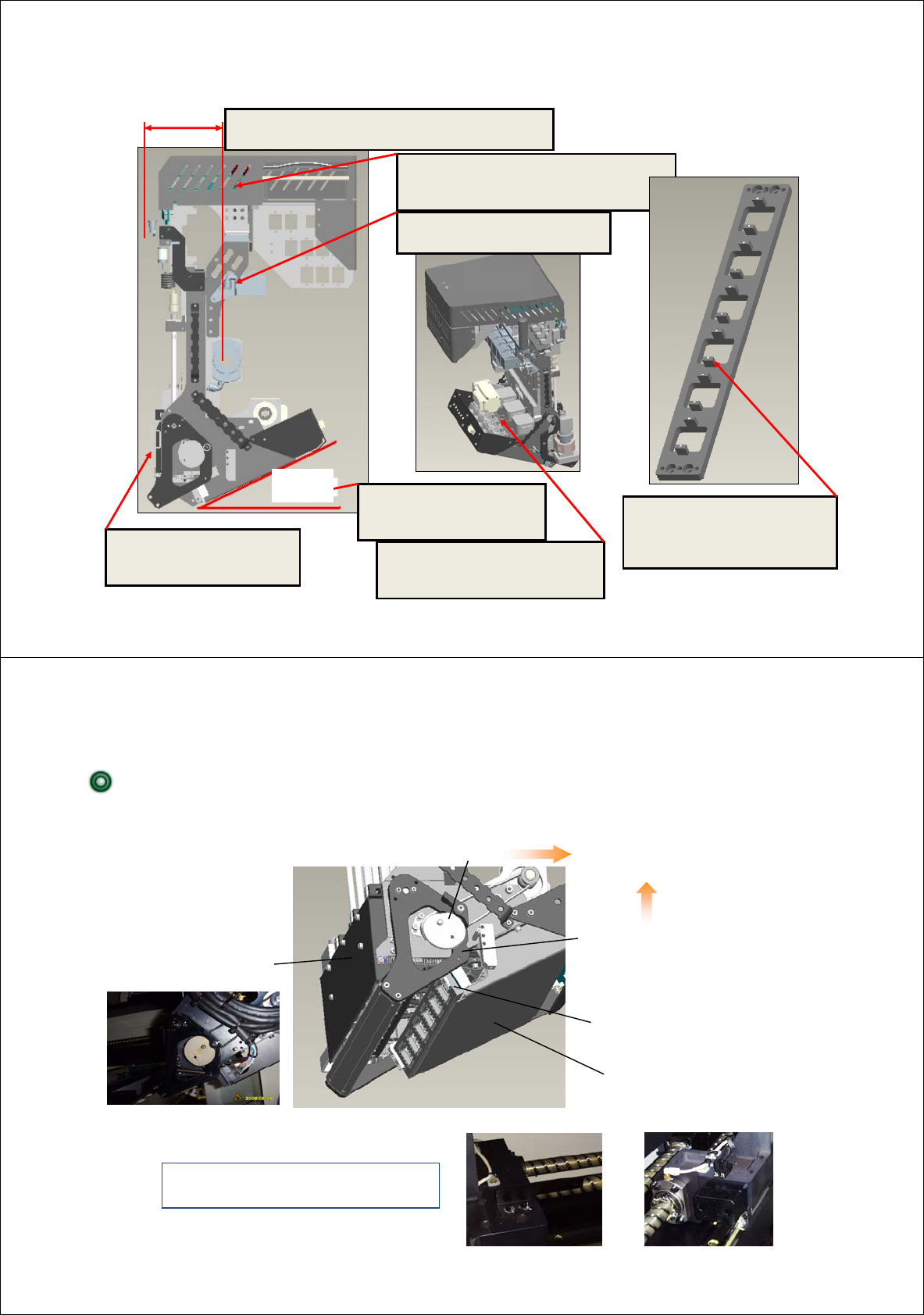
Main improvement – Head
Improvement of placement
precision by recognizing
simultaneously with reference
mark when recognizing parts.
Individual camera is directly
assembled to the head main
frame.
Placement view obtained
from front by arranging the
fly camera with inclination
Cost reduction by removing
the ascending/descending
part of side illumination
Prevention of board damage by external
force resulted from separation of head
related board and instruments.
Improvement of grease
application to X driving part
Sol block’s arrangement in the rear to obtain
minimum space for 2-gantry approach
7
View
obtained
(SM411)
Main improvement – Head
8
CAM BRACKET ARM
COVER
OUTTER Light Position
COVER
CAM
Additional Spacer
Crash Sensor length was chagned.
Changed collision avoidance area
by Head mechanism change
Head mechanism modification for Max □ 42mm , Thickness 12mm component
SM411F has several changed parts In comparison with SM411
(SM411F)
to avoid the interference
between a component and mirror