SM411F_Service Manual.pdf - 第98页
The reference values for the calibration of th e Head Reference Fiducial Offset is as follows Offset X : -0.50 ~ 0.50 (m m) Offset Y : -0.50 ~ 0.50 (mm)
The result value can be confirmed in the Camera dialog box in the System
Setup menu.
The reference values for the calibration of the Head-Fly Offset is as follows.
(Mega FOV 15)
Offset X : -0.45 ~ 0.45 (mm)
Offset Y : -0.45 ~ 0.45 (mm)
Offset R : -1.0° ~ 1.0°
The reference values for the calibration of the Head-Fly Offset is as follows (Mega
FOV 16)
Offset X : -0.60 ~ 0.60 (mm)
Offset Y : -0.60 ~ 0.60 (mm)
Offset R : -1.0° ~ 1.0°
"Memo

The reference values for the calibration of the Head Reference Fiducial Offset is as
follows
Offset X : -0.50 ~ 0.50 (mm)
Offset Y : -0.50 ~ 0.50 (mm)
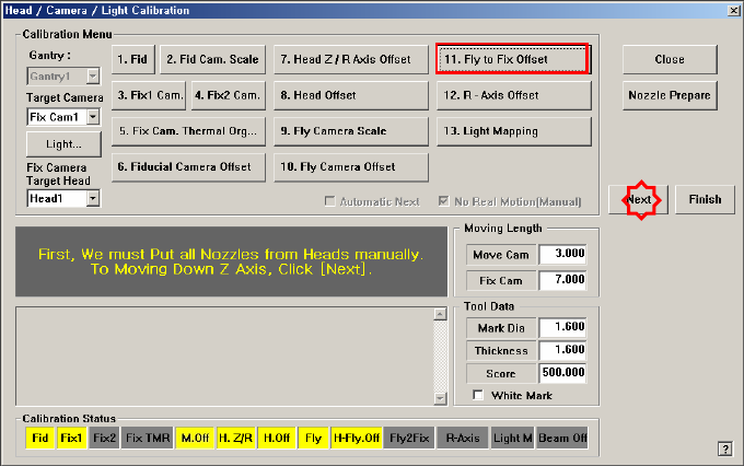
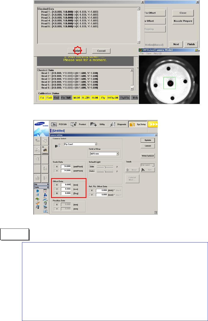
1.2.10.7. Fly to Fix Camera & Fly Runout Offset Calibration
Calibrates the relation between the Fly camera and Fix camera. The calibration is
performed to compensate the offset that occurs due to the difference between the
‘part-alignment height’ and placement height when placing the part after part-
recognition by the fly-camera.
The offset that occurs this time is caused by the run-out, bending of an axis, etc.
Perform compensation of the value at the recognition height of the fly camera and
fiducial camera, which are the same as the placement height.
In order to perform this calibration, the ‘Fly-Camera Offset Calibration’, ‘Fix-
Camera Scale Calibration’ and ‘Head Offset Calibration’ must be performed first
and the CNT20 nozzle must be used.
The following is the procedure to calibrate the ‘Fly to Fix Offset’.
1. Click the <Nozzle Prepare> button and insert the CNT20 nozzle into the No. 1
hole of the ANC manually.
If the <11. Fly to Fix Offset> is clicked after selecting the <Automatic Next>
check box, calibration is performed for the selected gantry automatically.
If calibration is performed after selecting the <No Real Motion [Manual]>
check box, the nozzle is inserted into each head manually. Click the <Next>
button to move onto the next step.
If calibration is performed without selecting either the <Automatic> check box
or <Manual> check box, the nozzle is changed automatically for the currently
selected nozzle. Click the <Next> button to move onto the next step.
2. If the <11. Fly to Fix Offset> button is selected, the message “First, We must
Put all Nozzles From Heads on Manually. To Move down Z Axis, Click [Next]”
appears. Click the <Next> button to move down the Z-axis of the head in order
to manually move all nozzles inserted in the nozzle-holder of the head.
3. Then, after the head assembly moves to the designated position, move all Z-
axes down. At this time, remove all inserted nozzles manually.
4. Then the message “Next Attach the Calibration Tool to Head 1. Click [Next]
for Moving Down Head. After Moving, Attach the Tool to Head Manually”
appears. Click the <Next> button after inserting the CNT20 nozzle in the
nozzle-holder of Head #1 manually.