SM411F_Service Manual.pdf - 第81页
The following is the procedure to calib rate the Fid Cam Offset of the head; 1. If the <6. Fiducial Came ra Offset> button is clicked, the me ssage “First, W e must Put all Nozzles From Heads on Manually . T o Move…
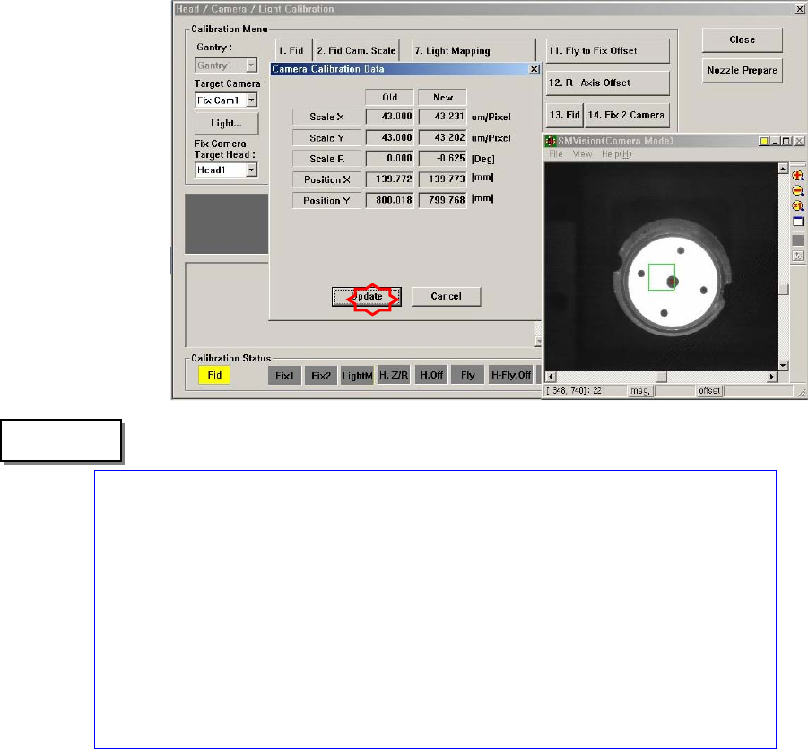
The range of the reference values for the ‘fly-camera calibration’ is as follows:
Mega FOV 35
ScaleX:32.7~34.6 (μm/pixel)
ScaleY: 32.7~34.6 (μm/pixel)
R:-1~1(deg)
Mega FOV 45
ScaleX:42.3~44.2 (μm/pixel)
ScaleY: 42.3~44.2 (μm/pixel)
R:-1~1(deg)
1.2.10.2. Fiducial Camera Offset Calibration
Measure the offset between the center of the fiducial camera and the first head
(Head 1, Head7) of each gantry.
This offset measurement must be completed to be able to use the Auto Nozzle
Change function for calibrations that follow. This process is performed only in the
Manual Mode.
In order to perform calibration of Fly-Camera Scale Calibration, first check if the
calibration tool is placed on the calibration tool position of the front ANC.
"Memo
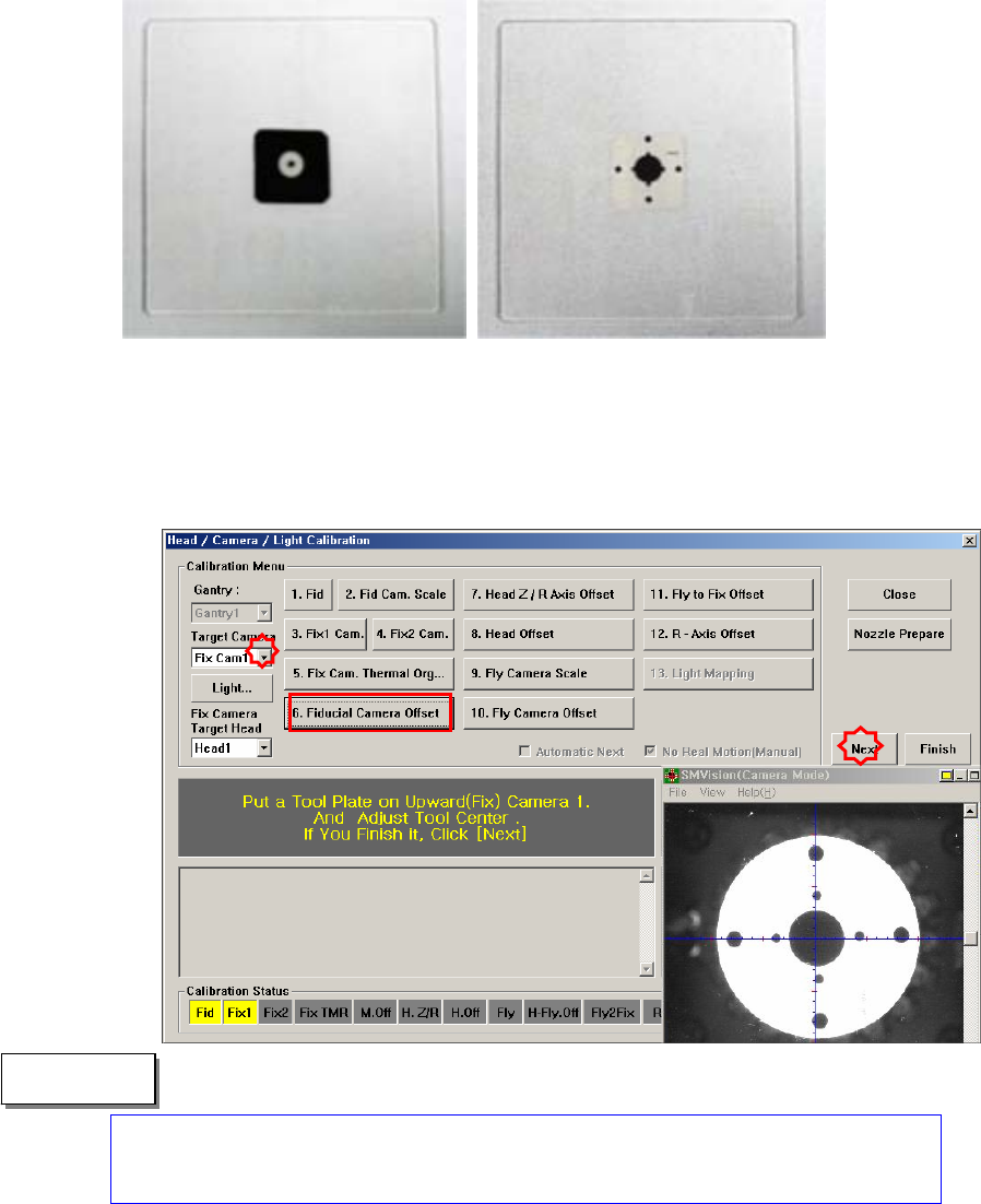
The following is the procedure to calibrate the Fid Cam Offset of the head;
1. If the <6. Fiducial Camera Offset> button is clicked, the message “First, We
must Put all Nozzles From Heads on Manually. To Move Down Z Axis, Click
[Next]” appears in the message box. Click the <Next> button to move down
the Z axis of the head in order to remove all nozzles inserted in the nozzle-
holder manually.
Only when the Calibration Glass is properly aligned with the center of the Fix
Camera can calibration be performed. Place the Calibration Glass correctly
referring to the following figure.
" Memo
2. “The message, “Move To Center Position of [Fix 1] Camera. To Move, Click
[Next]” is displayed in the message window. Click the <Next> button to move
the head assembly to the center of the Fix 1 Camera.
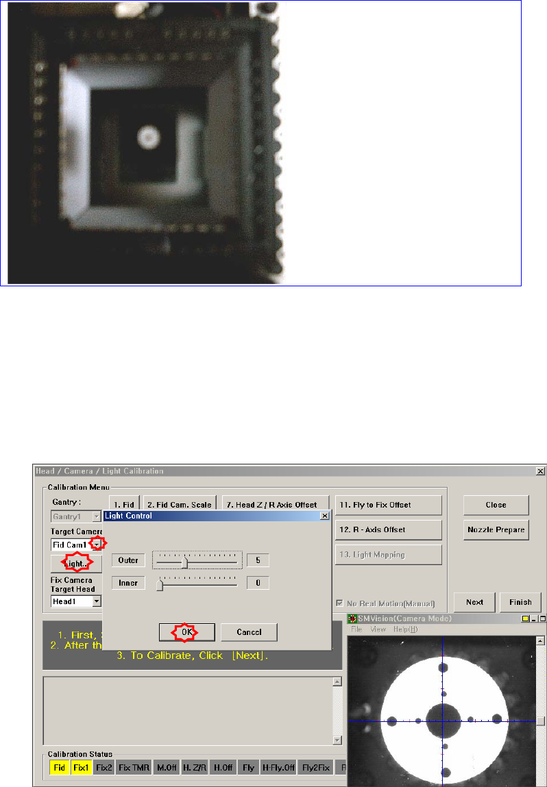
3. The message “1. First, Select Move Camera and Adjust Light Level. 2. After
that, Select Fix-camera and Adjust Light Level. 3. To Calibrate, Click [Next]”
appears. Then click the <Light…> button first and adjust the brightness of the
light in the Light Control’dialog box so that the white circle at the center of the
Calibration Glass that is seen in the ‘SMVision’ window can be seen clerly.
4. Then select the ‘Fix1 Cam’ in the <Target Camera> combo box and click the
<Light…> button. Adjust the brightness of the light in the ‘Light Control’
dialog box so that the fiducial mark on the Calibration Glass that is seen in the
‘SMVision’ window can be seen clearly. Click the <Next> button.