SM411F_Service Manual.pdf - 第26页
Entry and exit shuttl e assy. 11 Rear rail Front rail PCB sensor Shuttle base Width trimming driving part Transfer belt driving part Shuttle driving part PCB stopper (SM411) Width trimming of shuttle and composition of s…
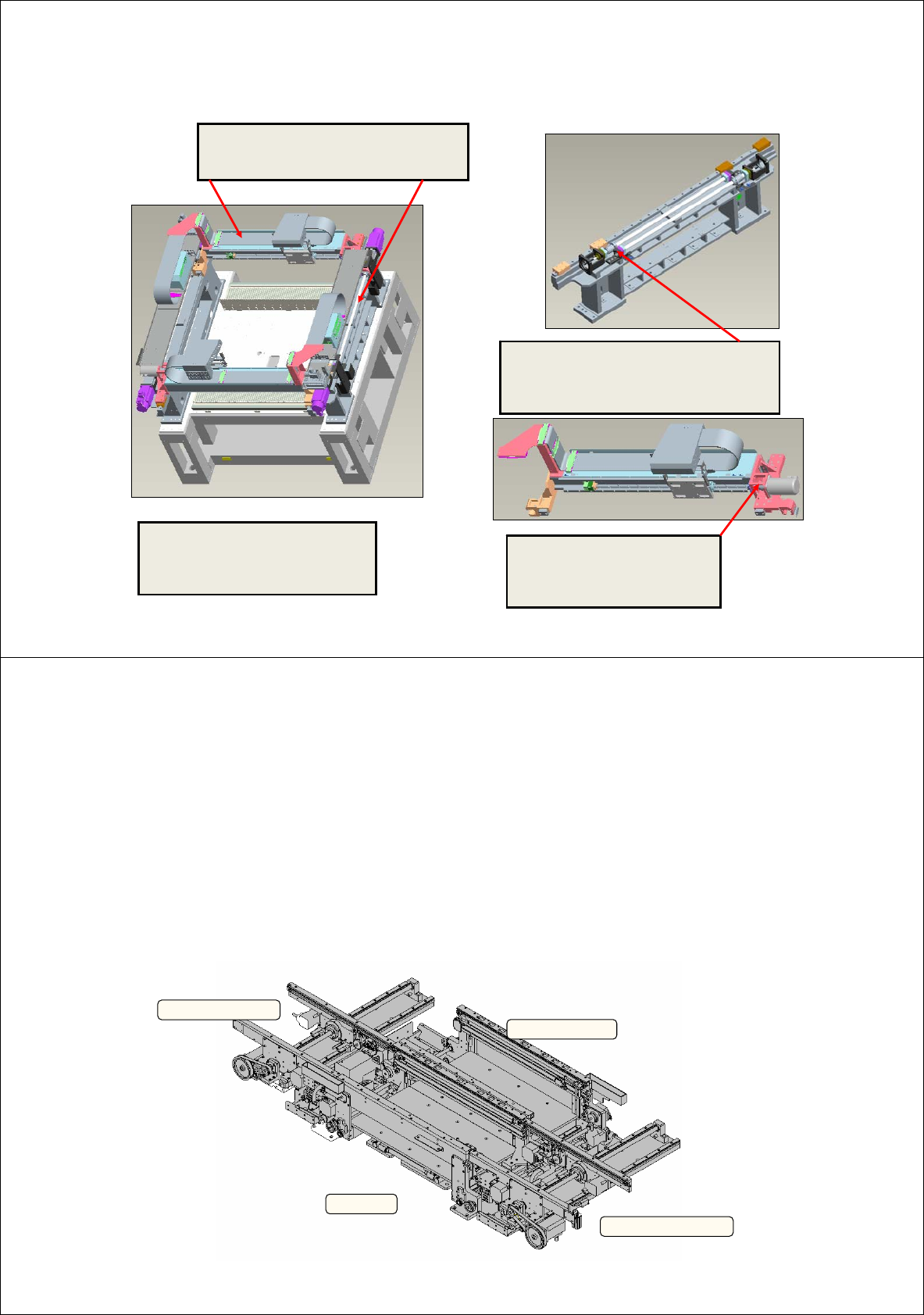
Main improvement – X-Y
The assembly precision is
improved by obtaining
concentricity of X-motor and
b/screw.
Improved assembling ability by pin
assembly of X-Y assy. (Assembly
clearance by processing is obtained)
To prevent modification after assembling
in module unit, the structure is improved to
simply assemble Y-b/screw after
assembling X-Y body.
Improvement of grease application
method to Y driving part
(The difficulty of approach is solved
when applying grease to 2-gantry)
9
z Structure
• ENTRY SHUTTLE ASSY : Composed of front and rear moving rail. Performs width trimming and shuttle
movement with one ball screw and two motors.
• WORK ZONE ASSY : Composed of front and rear placement zone. Performs width trimming with lead
screw and motor and performs PCB settling function in relation with BUT.
• EXIT SHUTTLE ASSY : Composed of front and rear moving rail. Performs width trimming and shuttle
movement with one ball screw and two motors.
• Composed of dump box and cable wiring related parts.
EXIT SHUTTLE ASSY
ENTRY SHUTTLE ASSY
WORK ZONE ASSY
BUT ASSY
10
Improvement – Conveyor
(SM411)
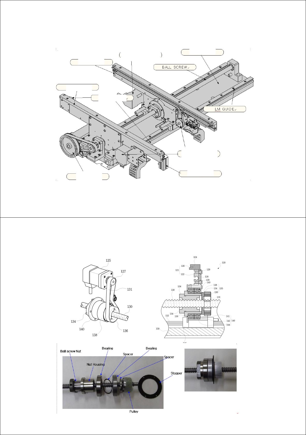
Entry and exit shuttle assy.
11
Rear rail
Front rail
PCB sensor
Shuttle base
Width trimming
driving part
Transfer belt
driving part
Shuttle
driving part
PCB stopper
(SM411)
Width trimming of shuttle and composition of
shuttle driving part’s ball screw
12
(SM411)
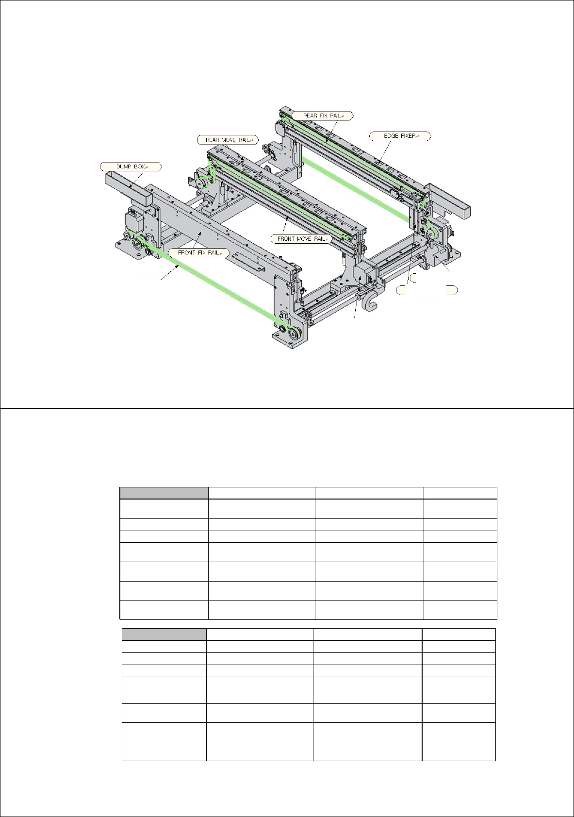
Main parts of work zone assy.
13
Lead screw
synchronous belt
Belt driving motor
Stopper
Width trimming motor
(SM411)
Specification
Long When using dual lane When using single lane Remarks
Max. PCB 610L*250W 610L*460W
Min. PCB 50L*40W 50L*40W
Transformable PCB load ~2Kg ~2Kg
Corresponding range of
PCB thickness
0.38~4.2mm 0.38~4.2mm
Size including PCB
bending
Part corresponding
clearance
Top 15mm, Bottom 25mm Top 15mm, Bottom 25mm
Max. design speed of belt 256~508 mm/sec 256~508 mm/sec
Variable according to
PCB weight
Position compensation
device
Edge fixer Edge fixer
Standard When using dual lane When using single lane Remarks
Max. PCB 460L*250W
510L*460W (Buffer unavailable)
460L*460W (Buffer available)
Min. PCB 50L*40W 50L*40W
Transformable PCB load ~2Kg ~2Kg
Corresponding range of
PCB thickness
0.38~4.2mm 0.38~4.2mm
Size including PCB
bending
Part corresponding
clearance
Top 15mm, Bottom 25mm
Top 15mm, Bottom 25mm
Max. design speed of belt 256~508 mm/sec 256~508 mm/sec
Variable according to
PCB weight
Position compensation
device
Edge fixer Edge fixer
14
(SM411)