SM411F_Service Manual.pdf - 第45页
180 ˚ Po s i t ion Home Positi on Idler w hee l Driv ing axis Mark Sw i ng M i r r or Cam 6. Check if the centers of the 3 circles ar e aligned by using a general ruler . 7. Ensure safety when performing visual checking.…
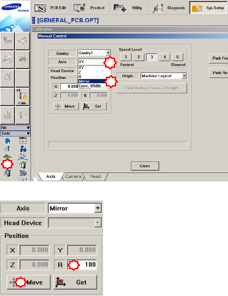
3. Select the ‘Manual Tool’ in the ‘Tools’ shortcut menu and select the ‘Mirror’ in
the <Axis> combo box of the ‘Manual Control’ dialog box.
4. Select the <R> edit box in the <Position> group of the ‘Manual Control’
dialog box and input ‘180’ in it. Then click the <Move> button.
5. When the three points (idler wheel, CAM driving axis and mark) in the
following figure are not aligned, align them by rotating the cam using the
teaching box as shown in the following figure. At this time, the position is
called “180 degrees”.
1
2
3
1
2
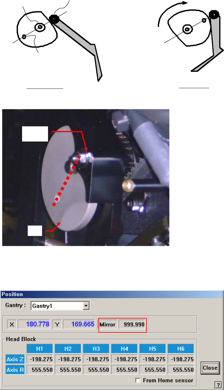
180˚Position
Home Position
Idler wheel
Driving axis
Mark
Swing Mirror
Cam
6. Check if the centers of the 3 circles are aligned by using a general ruler.
7. Ensure safety when performing visual checking. At this time, the
corresponding user must manipulate the machine.
8. Check the mirror data displayed in the ‘Current Position’ dialog box. Then,
measure and input the offset values as shown in the following figure.
Cam
Followe
r
Ca
m
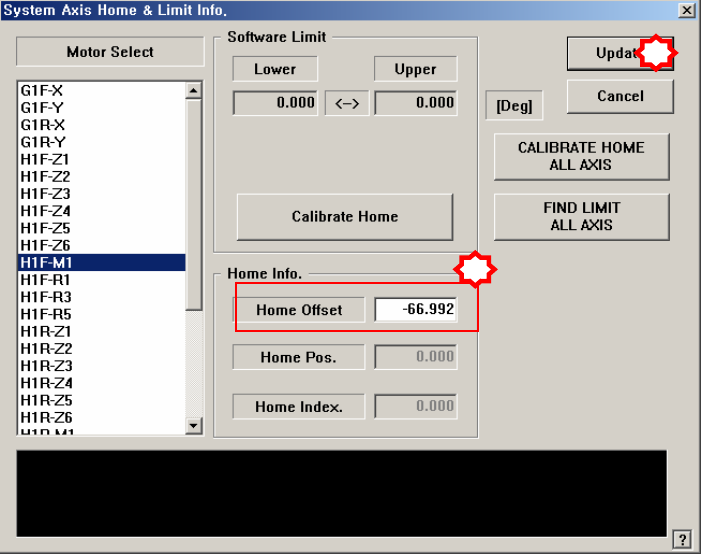
9. In the <Home Offset> edit box of the ‘System Axis Home & Limit Info.’
dialog box, input the value that was obtained after subtracting “180” from the
mirror value in the ‘Position’ dialog box in the above figure.
10. After finishing the input, click the <Update> button to reflect the changed
value.
11. Then select “No (N)” when prompted by the screen asking whether to perform
the homing of the machine.
12. Perform homing of the machine by using the teaching box.
1
2