SM411F_Service Manual.pdf - 第36页
[4-3] 조립성개선관련 z z Simplification of wiring th rough new axis sensor board Simplification of wiring th rough new axis sensor board 31 ◆ Construction of SM411(F) PC & VME control rack [5] CONTROL RACK 및 제어보드구성 1 2 3 5 …
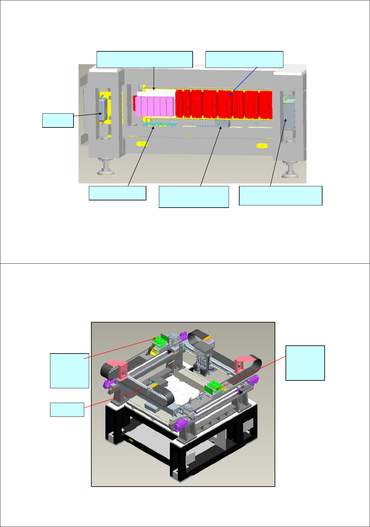
[3-2] Layout of rear wiring harness
- Servo Driver for X,Y and SW 8EA
(PANASONIC servo driver)
- For moving conveyor width/shuttle
Stepping driver 6EA(SANYO PB driver)
Distribution of AC power supply
(CP, MC, terminal block)
Main noise
filter
Safety control and DC
power board
-Stepping driver for conveyor belt
driving 4EA(8 axis) (Newly developed
by CONVEX)
29
[3-3] Layout of top wiring harness
Z axis-driver
box mounted
2-stage, 3-
row: 6 EA
(Rear gantry)
Flat cable
used
Zaxis-driver
box mounted
2-stage, 3-
row: 6EA
(Front gantry)
30
[4-3] 조립성개선관련
z
z
Simplification of wiring through new axis sensor board
Simplification of wiring through new axis sensor board
31
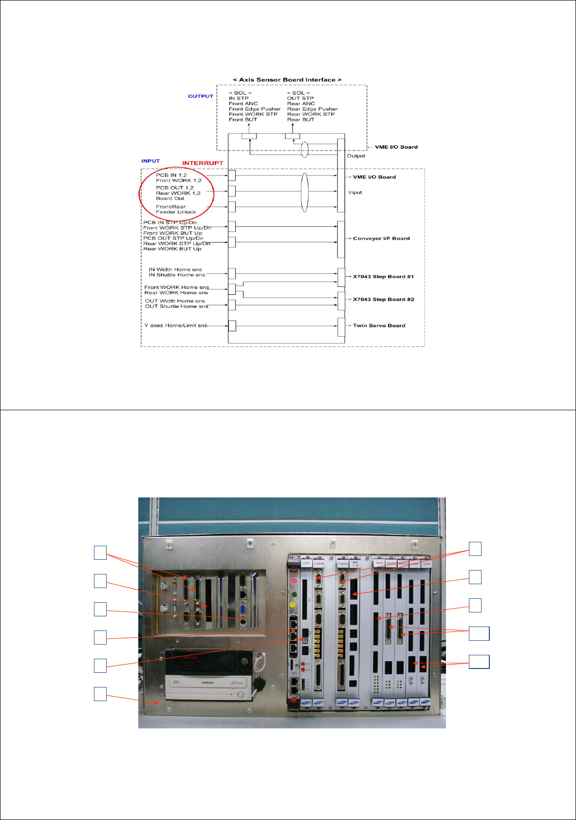
◆ Construction of SM411(F) PC & VME control rack
[5] CONTROL RACK 및 제어보드구성
1
2
3
5
6
7
8
9
10
11
NEXTEYE IMAGE Board
PCI IO Board
SBC Board(P-4 Dual Core)
CPU Board( Power CPU)
SM330 CAN MASTER Board
SM330 VME IO ILL Board
SM321 Vision IF Board
SM330 Twin Servo Board
X7043 SEDES Board
X7043 STEP CON. Board
4
PC & VME Rack Ass’y
32

[5-1] CONTROL RACK –PC Part
SM411(F) CONTROL RACK ASSY - PC Part
◆ Composition of PC part
#1 SAMC-62 Image Board
(Common use for SM321)
Æ Image board for gantry #1 and #2 (Fly Cam 1 - 6, Fiducial Cam 1)
#2 PCI I/O Board (Common use for SM321)
Æ DP-ram communication board between PC part and VME part
#3 SBC (Single Board Computer) Board
Æ SBC board for SM321 and SBC board for P-4D
#4 PC & VME RACK ASS’Y
Æ Common use for SM320 and SM321
Others : Examination of PC power supply upgrade
33
[5-2] CONTROL RACK –VME Part
SM411(F) CONTROL RACK ASSY - VME Part
◆ Composition of VME part
- Cable optimization, cost reduction, optimization of control board and
new concept design
#5 VME CPU Board (Motorola E3100 Board)
#6 SM411 CAN Master Board (Common use for SM321 + placement by adding part)
Æ Gantry #1 use CAN1 and #2 CAN2 (placement by adding part of communication
sector)
#7 Vision I/F Board (Common use for SM321)
Æ Vision I/F board for gantry #1 and #2 (Fly Cam 1 - 6, Fiducial Cam 1)
#8 VME I/O & ILL Board for SM411(F)
Æ Gantry #1, 2 Vacuum and Blow I/O + Other IO (Addition of I/O port)
Æ Stage Camera(front,rear) Light Control(SM411F only)
#9 New Twin Servo Board
Æ Gantry #1,2 Skew Monitoring, Gantry Collision Avoidance
Æ Synchronization control of FY1-FY2 and RY1-RY2 axis
34