SM411F_Service Manual.pdf - 第51页
1.2.2. Skew compensation Skew means compensating the skew occu rred horizontally in t he X-axis frame against the Y1-axis and Y2-axis after movement of equipment. This m ust be done upon initial installation and after mo…
<FIND LIMIT ALL AXIS> button
Finds the Limits of all axes.
<Home Info.> Group
If the mirror axis is selected, the <Home Offset> edit box will be enabled. It is
used to perform calibration for the mirror axis.
<Update> button
Transmits the set data to the machine and closes the dialog box.
<Cancel> button
Ignores the set data and closes the dialog box.
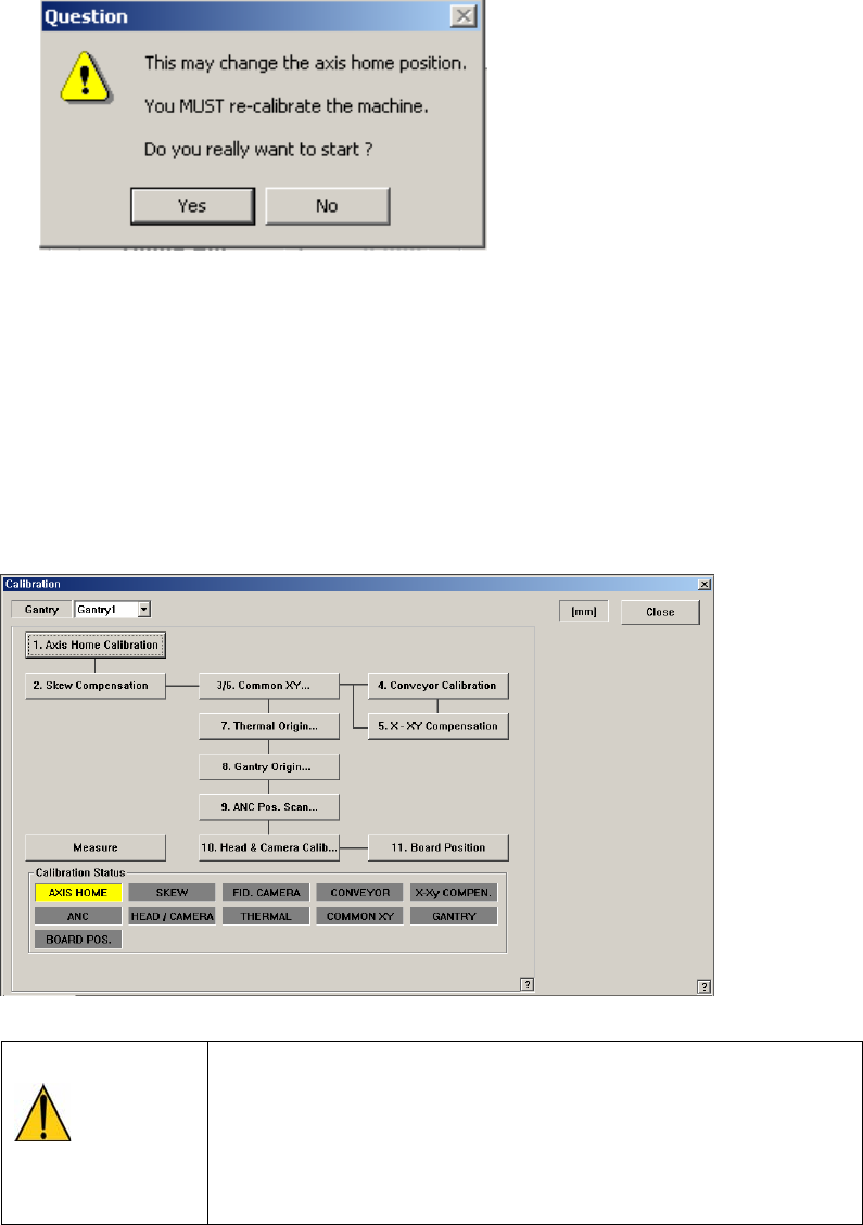
Caution
If calibration is done again, the machine might not operate
properly unless the items related to the equipment position,
such as pick up position, ANC, placement origin are taught
again as the home position is changed.
After calibration, be sure to teach the items related to
position again.
1.2.2. Skew compensation
Skew means compensating the skew occurred horizontally in the X-axis frame
against the Y1-axis and Y2-axis after movement of equipment. This must be done
upon initial installation and after movement of the equipment to a new location.
Method of skew compensation for Y-axis is as follows;
Caution
<Skew Compensation> must be performed before ‘return to
origin’ following initial installation or movement of
equipment. Otherwise, the equipment may be damaged
during operation.
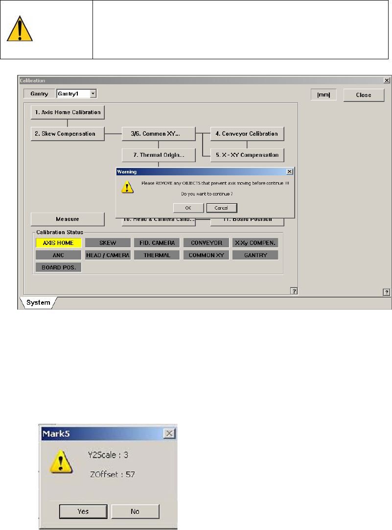
First, move the X frame manually to the center of equipment.
Click on the <Skew compensation> button. Automatic homing on Z-axis is
performed, Y1-axis motor rotates and moves X frame until detecting the Y
home sensor. Once the home sensor has been detected, move to the Y-axis
movement distance (Y Stroke) in the opposite direction, and move to the
opposite direction again until the Y Home sensor is detected.
Then, ‘Skew’ information is shown as follows, and asks whether to apply the
value.
Click on the <Yes(Y)> button and <Update> button, and then homing of the
equipment is newly done in accordance with the applied skew information.
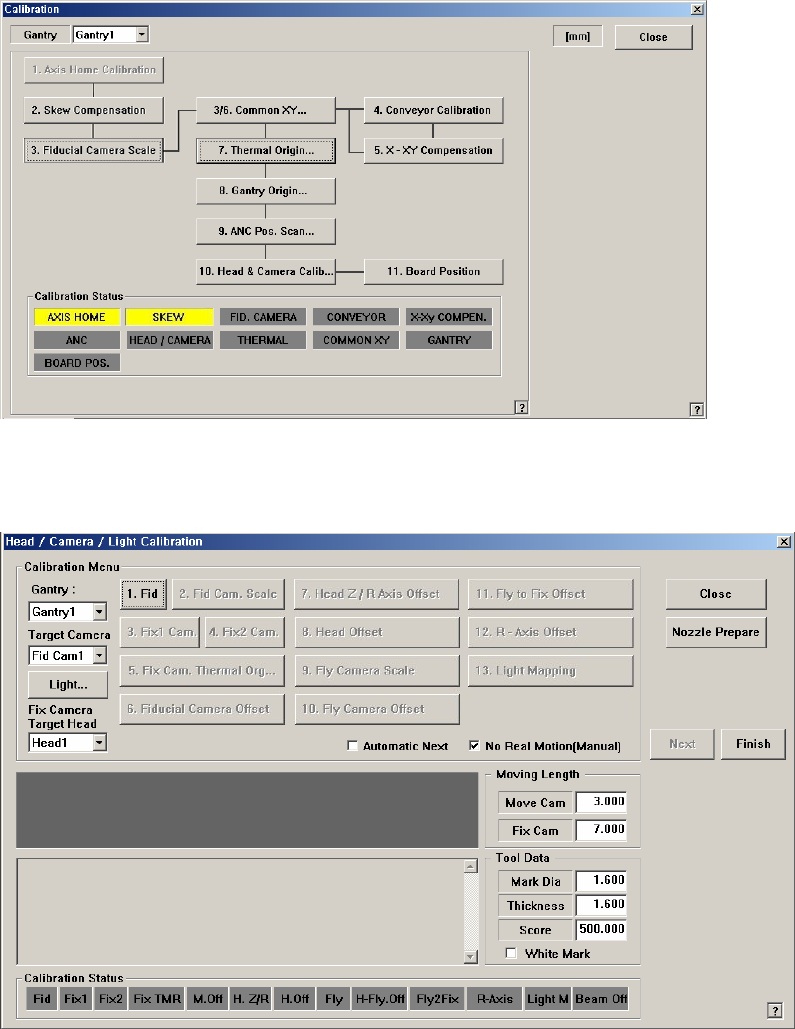
1.2.3. Fiducial Camera Scale Calibration
If the fiducial camera is not calibrated, the rest of the buttons are disabled.
<1. Fid> button
Teach the position of the Reference fiducial mark located at the top surface of
the ANC.
The following is the process that performs teaching of the calibration tool
placed on the top surface of the ANC by using the Reference fiducial camera.
1. When performing the mark setup, select the gantry and click the <1. Fid>
button. If the following screen appears, click the <Move> button in the
<Teach> group.
Then the fiducial camera moves to the corresponding position. The mark
ID of Gantry 1 is fixed as No. "7", and No. "8" for Gantry 2.