SM411F_Service Manual.pdf - 第43页
1.1. Mirror offset check and correction The swing mirror offset must be set up so that the image that is shown in the fly- camera through the mirror may be seen correctly . The following is the proceduer to set the offse…
Chapter 1. Calibration
This section describes the calibration process that must be performed after
installing the machine and performing warm-up.
The following are the works to be performed before performing calibration or those
to be performed in advance;
I/O Test
Mirror offset check and correction
Nozzle check and vacuum check option for system constant
ANC type check
Pneumatic system check for any problem
1
2
3
4
1.1. Mirror offset check and correction
The swing mirror offset must be set up so that the image that is shown in the fly-
camera through the mirror may be seen correctly.
The following is the proceduer to set the offset of the ‘swing mirror’;
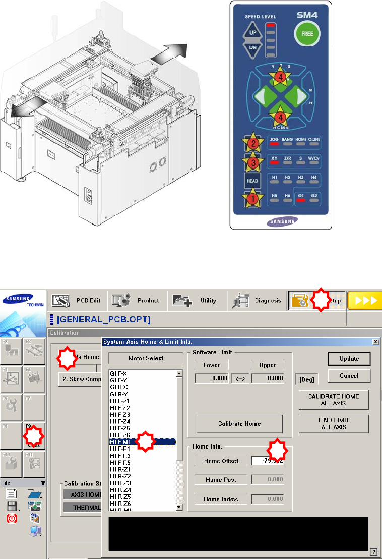
1. Manipulate the teaching box to move the head assembly to both ends as much
as possible.
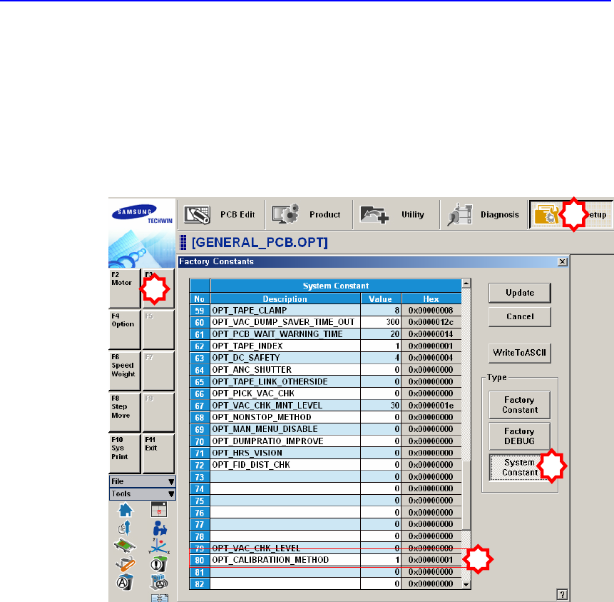
2. Select the ‘Calib’ submenu from the ‘Sys Setup’ menu. and Click the <1.Axis
Home Calibration> button and then select the ‘H1F-M1’ in the ‘System Axis
Home & Limit Info.’ dialog box (The ‘System Setup Factory’ menu can be
accessed only when the login must be done in service mode).
1
2
3
5
4
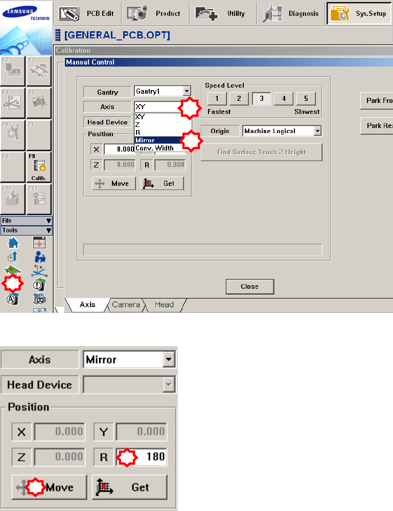
3. Select the ‘Manual Tool’ in the ‘Tools’ shortcut menu and select the ‘Mirror’ in
the <Axis> combo box of the ‘Manual Control’ dialog box.
4. Select the <R> edit box in the <Position> group of the ‘Manual Control’
dialog box and input ‘180’ in it. Then click the <Move> button.
5. When the three points (idler wheel, CAM driving axis and mark) in the
following figure are not aligned, align them by rotating the cam using the
teaching box as shown in the following figure. At this time, the position is
called “180 degrees”.
1
2
3
1
2