SM411F_Service Manual.pdf - 第65页
1.2.6. X-XY Compensation This is performed to compensate the XY e rror that occurs while moving the X axis. If the thermal mapping and gantr y mapping have already been enabled, disable the mapping by force to perform th…
13. After finishing the teaching, click the <Update> button to apply the changed
value.
F3_Ref# F3_Ref#
1.2.6. X-XY Compensation
This is performed to compensate the XY error that occurs while moving the X axis.
If the thermal mapping and gantry mapping have already been enabled, disable the
mapping by force to perform the X-XY compensation.
Caution
X-XY compensation is performed at the factory before the
machine is shipped. An exclusive calibration tool is needed
to perform this calibration.
In general cases, skip this calibration process and perform
the next calibration process.
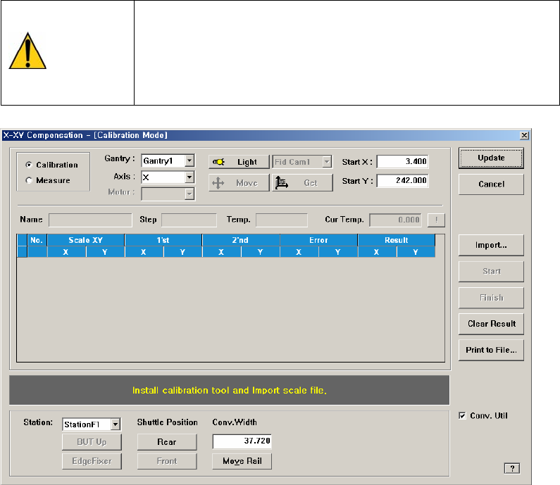
Figure 1-5. "X-XY Compensation" dialogbox
Mode Option button
Select the mode in which this process is to be performed.
<Calibration> Option button
Perform the X-XY compensation in the calibration mode and reflect the
result.
<Measure> Option button
Perform the X-XY compensation in the measurement mode and do not
reflect the result. It is selected to measure the error for the Y axis.
<Gantry> combo box
Gantry1: When performing calibration in Station F2 by using the calibration
tool.
Gantry2: When performing calibration in Station R2 by using the calibration
tool.
<Axis> combo box
Select the axis to be compensated. Compensation can be made only for the X
axis.

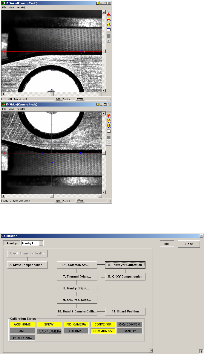
<Light> button
It is used to adjust the illumination so that the mark may be viewed clearly
when recognizing the fiducial mark of the calibration tool.
<Move / Get> button
It is used to teach fiducial mark #0 of the calibration tool.
<Start X / Start Y> editbox
Input the coordinate of fiducial mark #0 of the calibration tool. After selecting
the edit box, move the fiducial camera to the corresponding position by using
the teaching box and teach the corresponding mark correctly. Then click the
<Get> button and input the coordinate value here.
<Cur Temp> editbox
Input the current temperature at the time that the calibration is performed.
<Station> combo box
It is selected to put the calibration tool to the corresponding station. Select the
station and click the <Move Rail> button and adjust the conveyor width.
<BUT Up / Down> button
Put the calibration tool to the corresponding station and click the <BUT Up>
button to move up the BackUp Table.
If the calibration is completed, click the <BUT Down> button and move down
the BackUp Table. Then remove it from the corresponding station.
<EdgeFixer> button
Put the calibration tool to the corresponding station and move up the BackUp
Table. Then click this button to secure the calibration tool.
Once the calibration is completed, click this button to release the securing of
the calibration tool.
<Front / Rear> button
Once the calibration is completed in Station F2, it is used to move Station F1 to
the rear lane in order to put the calibration tool to Station R2.
Caution
Before moving the shuttle, the exclusively used calibration
tool must be removed from the corresponding station.
<Import…> button
It is used to import the scale file for calibration.
<Start> button
It is used to start calibration after teaching fiducial mark #0 accurately.
<Finish> button
It is used to exit the work after the calibration is completed.
<Print to File…> button
It is used to output the result in text file format after completing calibration.
<Conv. Util> checkbox
Always use this as is selected.