SM411F_Service Manual.pdf - 第165页
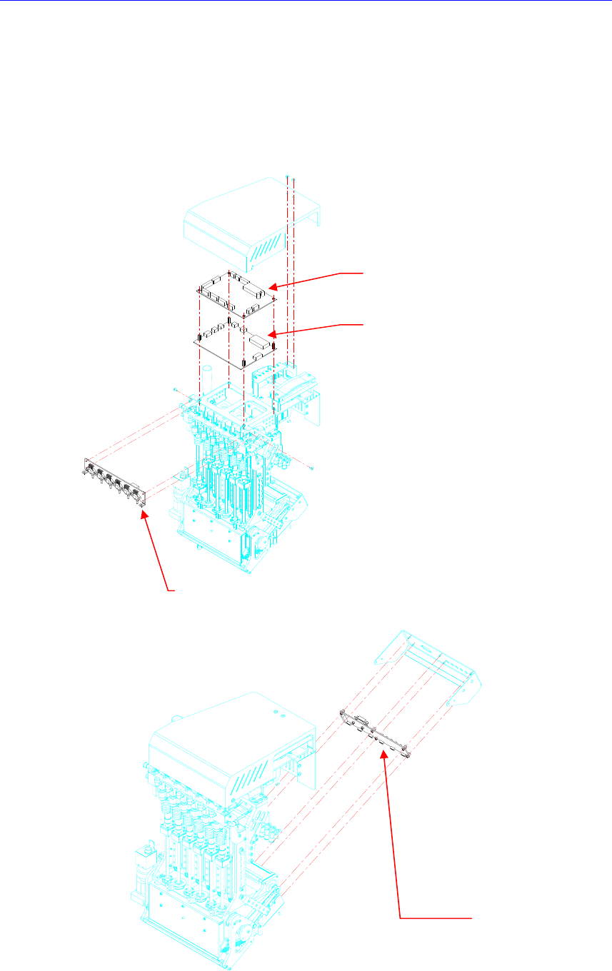
Electric Device CAN Head Illumination Board CAN Head I/O Board V acuum Sensor Board Camera I/O Board 3.4.2. Required T ools Spanner Screw driver with “ + ” shaped tip and screw driver with “ - ” shaped tip …
Electric Device
3.4. Head Module Board Assembly
3.4.1. Representative Cases to Replace the Head Module Board Assembly
MPU-Stop error occurred (CAN HEAD I/O BOARD)
Defective operation of various sensors/cameras on the head (CAN HEAD I/O
BOARD)
Defective various illuminators on the head (CAN HEAD ILL BOARD)
C
AN H
e
a
d
I
/O
B
o
ar
d
CAN Head
Illumination Board
Vacuum Sensor Board
C
am
e
ra I
/O
B
o
ar
d

Electric Device
CAN Head Illumination Board
CAN Head I/O Board
Vacuum Sensor Board
Camera I/O Board
3.4.2. Required Tools
Spanner
Screw driver with “+” shaped tip and screw driver with “-” shaped tip
T Wrench or Hex Wrench
Electric Device
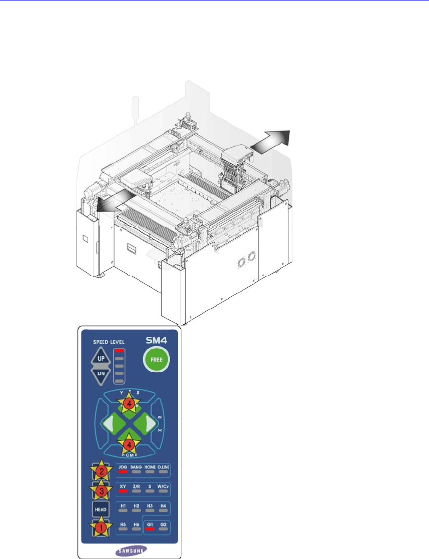
3.4.3. Head Module Board Replacement Procedure
CAN Head Illumination Board/ CAN Head I/O Board
1. Manipulate the teaching box to move the head assembly to both ends as much
as possible.
2. Turn Off the PC in normal way. Then turn off the main switch on the front side
of the machine.