00193370-0202.pdf - 第46页
Handbuch für das Achsprüfgerät / Axis T ester Manual SIPLACE Axis T e ster 9 W artung Ausgabe 08/2003 Edition 46
SIPLACE Axis Tester Handbuch für das Achsprüfgerät / Axis Tester Manual
Ausgabe 08/2003 Edition 9 Wartung
45
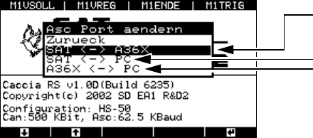
8.5.4.2 Menü "Asc-Anschluss"
Æ Wählen Sie im Menü "Anschlüsse" das Menü "Asc-Anschluss" und danach "Asc-Port ändern".
Das Menü "Asc-Port ändern" wird eingeblendet.
Abb. 8 - 56 Menü "Asc-Port ändern"
SAT ↔ A36X
Als Standardeinstellung ist immer die Verbindung Achsprüfgerät – Achsansteuerung konfigu-
riert. Die Signalübertragung erfolgt über das Flachbandkabel.
SAT
↔ PC
Wählen Sie diese Einstellung, wenn Sie einen Software-Update des Achsprüfgeräts durchfüh-
ren wollen.
A36X
↔ PC
Bei dieser Konfiguration ist das Achsprüfgerät der Mittler zwischen Achsansteuerung A36X
und dem PC, der an die neunpolige SUBD-Buchse angeschlossen ist. Mit Hilfe von Program-
men können Sie Daten, z.B. Zählerstände, Zustandsbytes aus der Achsansteuerung an einen
externen PC übertragen.
9 Wartung
Das Achsprüfgerät selbst ist wartungsfrei. Überprüfen Sie allerdings jährlich die Anschlusskabel,
insbesondere das Flachbandkabel auf
– Beschädigung der Isolation,
– Kabelbrüche und
– einwandfreie elektrische Verbindungen zwischen Flachbandkabel und Anschlusssteckern.
Wahl des Ports:
Achsprüfgerät – Achsansteuerung (Standard
)
Achsprüfgerät – PC
Achsansteuerung – PC
Handbuch für das Achsprüfgerät / Axis Tester Manual SIPLACE Axis Tester
9 Wartung Ausgabe 08/2003 Edition
46

SIPLACE Axis Tester Handbuch für das Achsprüfgerät / Axis Tester Manual
Ausgabe 08/2003 Edition 1 Overview
47
1Overview
To optimize your placement machine’s performance, you must first optimize the dynamic re-
sponse of the axes. Signals from the axis controller are tapped using an adapter board so that
they can be used for tests, settings and diagnosing errors. An oscilloscope connected to the
adapter board displays the signal traces for your diagnostics.
The new SAT (S
IPLACE Axis Tester) greatly simplifies the test set-up. There is just one ribbon
cable connecting the axis tester to the axis board. The tester can be connected to series A360,
A361 and A362 axis cards. The signal traces can be graphically represented on the display. The
tester can also read the register contents of counters in the axis controller board for diagnostic
purposes in order to identify counting errors by incremental position measuring systems, for ex-
ample.
The axis tester has “hot-plug” capability, which means that it can be connected to the axis control-
ler board without having to switch the machine off first.
The axis tester does not require a separate power supply. Instead, the control unit provides the
necessary + 5 VDC and ± 15 VDC voltages via the sockets on the axis controllers.
For communication, the axis tester has a CAN bus and a serial port. The CAN bus connection can
be used to send control signals to the head board or to check the status of these signals for diag-
nostic purposes, for example. The signals can be output for further analysis to measuring devices,
such as oscilloscopes, voltmeters, etc, via four freely assignable BNC sockets. The positioning
movements of the axes and other data that appears on the axis tester display can also be sent to
a plotter and printed out for documentation purposes.
A user-friendly menu structure allows the axis tester to be quickly configured for all required diag-
nostic tasks. Preprogrammed configurations tailored to each type of placement machine greatly
reduce the time required to build the test set-up and take the measurements. You can also store
your new test configuration for later use.