00193370-0202.pdf - 第62页
Handbuch für das Achsprüfgerät / Axis T ester Manual SIPLACE Axis T e ster 8 Using the menus Ausgabe 08/2003 Edition 62 Fig. 8 - 8 “Panel” menu, selecting the line (BNC socket) Æ Select a BNC sock et and pres s membrane …
SIPLACE Axis Tester Handbuch für das Achsprüfgerät / Axis Tester Manual
Ausgabe 08/2003 Edition 8 Using the menus
61
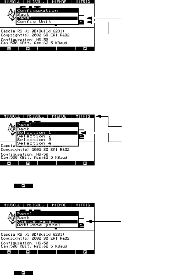
Fig. 8 - 5 “Configuration” menu
8.3.1 “Panel” menu
This menu is used to configure the four BNC output panels. Each is configured in a different win-
dow. You can assign 4 signals to each of the 4 BNC sockets from a choice of 30 available signals.
Fig. 8 - 6 “Panel” menu, selecting the panel assignment group
Æ Press to confirm the selected group, e.g. “Selection 1”. The next menu appears with
the “Change panel” and “Activate panel” options.
Fig. 8 - 7 “Panel” menu, “Change panel” option
Æ Press to confirm your choice of “Change panel”.
The menu for selecting the BNC socket appears.
Menu for assigning signals to
the BNC panels
Menu for configuring the signal sampling fo
r
the axis controllers
Assignment of the BNC sockets in the 1st
selection window
Selection window for the 1st panel assign-
ment group
To the “Change line 1 … 4” menu
Handbuch für das Achsprüfgerät / Axis Tester Manual SIPLACE Axis Tester
8 Using the menus Ausgabe 08/2003 Edition
62
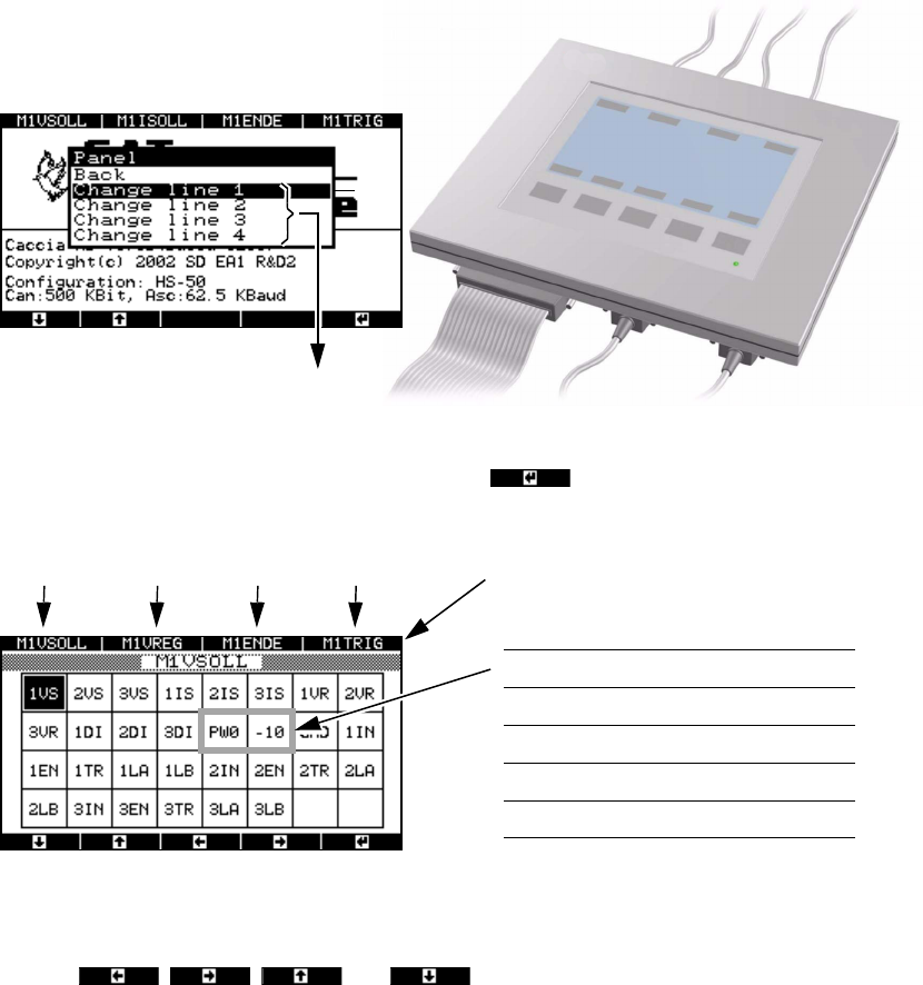
Fig. 8 - 8 “Panel” menu, selecting the line (BNC socket)
Æ Select a BNC socket and press membrane button .
A range of signals appears in the next window.
Fig. 8 - 9 “Panel” menu, range of available signals
The two bordered fields change according to the selection group.
Æ Use the , , and buttons to move the black mark in order to
select the required signal from the available choice.
BNC sockets 1 … 4
N
M
O
P
Signals
Selection 1 PW0 -10
Selection 2 PW1 5
Selection 3 PW2 BNC
Selection 4 PW3 GND
BNC1 BNC2 BNC3 BNC socket assignment BNC4

SIPLACE Axis Tester Handbuch für das Achsprüfgerät / Axis Tester Manual
Ausgabe 08/2003 Edition 8 Using the menus
63
Each axis controller module contains three axis controllers. They are counted starting from the
topmost axis controller, i.e. all the signals from the topmost axis controller starting at 1. The ab-
breviations used are as follows:
Æ Press to select the required signal.
Æ Assign the signals to the desired BNC sockets for the entire selection group.
Æ Press to move to the next menu.
*) 1 = Top axis controller, 2 = Middle axis controller, 3 = Bottom axis controller
1/2/3 VS
*)
V
setpoint
Setpoint voltage
1/2/3 IS
*)
I
actual
Actual current for
DC motor
1/2/3 VR
*)
V
REG
Total current for
three-phase AC motor
drive
1/2/3 DI
*)
Diagnostics pin
PW0 Pulse width-modulated signal for representing the
position deviation after the end signal from axis con-
troller 1
BNC 1 assigned
PW1 Pulse width-modulated signal for representing the
position deviation after the end signal from axis con-
troller 2
BNC 2 assigned
PW2 Pulse width-modulated signal for representing the
position deviation after the end signal from axis con-
troller 3
BNC 3 assigned
PW3 Pulse width-modulated signal, variable assignment BNC 4 assigned
- 10 - 10 VDC reference voltage
5 +5 VDC reference voltage
BNC BNC test input
GND Ground
1/2/3 IN
*)
Zero pulse (index)
1/2/3 EN
*)
End signal
1/2/3 TR
*)
Trigger signal
1/2/3 LA
*)
Track signal A (line A)
1/2/3 LB
*)
Track signal B (line B)