00193370-0202.pdf - 第49页
SIPLACE Axis T est er Handbuch für das Achsprüfgerät / Axis T est er Manual Ausgabe 08/2003 Edition 2 T he axis tester and its components 49 Fig. 2 - 2 Axis tester – bottom view M Connection fo r ribbon cable Connecti on…
Handbuch für das Achsprüfgerät / Axis Tester Manual SIPLACE Axis Tester
2 The axis tester and its components Ausgabe 08/2003 Edition
48
2 The axis tester and its components
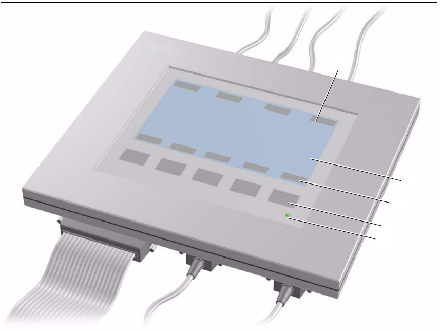
Fig. 2 - 1 Axis tester - plan view
M 240 x 128 pixel LCD display, black and white, backlit
The menus appear on the LCD display and the recorded trigger, track and position signals are
displayed graphically. All the relevant parameters, such as
- time base,
- measured times,
- amplitude scaling,
- signal level and
- cursor positions with the associated time differences
appear as alphanumeric information over the graphical representation of the measured curves.
N Dynamic function display for the BNC panel assignments on the LCD display
O Dynamic function display for the membrane key assignments on the LCD display
P Five membrane keys for menu control
Q Green operating display LED
N
M
O
P
Q
SIPLACE Axis Tester Handbuch für das Achsprüfgerät / Axis Tester Manual
Ausgabe 08/2003 Edition 2 The axis tester and its components
49
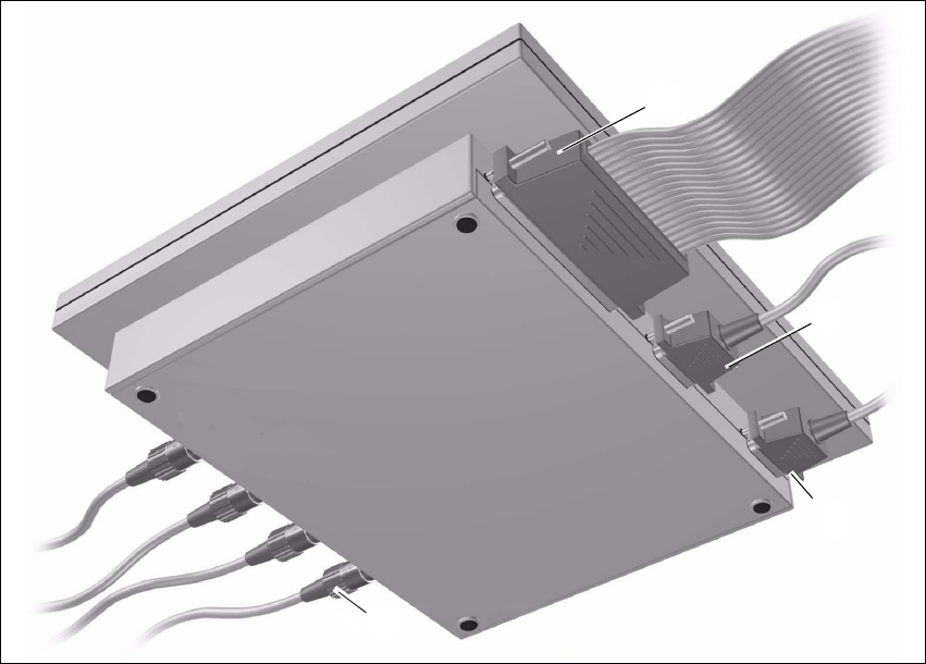
Fig. 2 - 2 Axis tester – bottom view
M Connection for ribbon cable
Connection on the axis tester: 37-pin sub-D connector
Connection on the axis controller:
– 37-pin sub-D connector for S-20/23/25/F4/F5 and HS-50 machines with A361 or A362 axis
controllers
– 25-pin sub-D connector for S-15/F3, G and wafflepack changer machines with A360 axis
controllers
An adapter is attached to the ribbon cable in order to connect the 25-pin axis controller.
The axis controller supplies the
+ 5 VDC ± 5 % and
± 15 VDC ± 5 %
operating voltages to the axis tester via the 37-pin ribbon cable.
N 9-pin sub-D connector for the CAN bus cable, e.g. for connecting CAN bus-controlled boards
in the placement machine (transmission speed 128 kBaud to 1 Mbaud, impedance 120 Ohm).
O 9-pin sub-D connector for the serial interface cable (V24), e.g. for connecting an external PC
(max. transmission speed 188 kBaud).
P Four BNC sockets, impedance 50 Ohm
The sockets can be assigned as required with the following signals:
M
N
O
P
Handbuch für das Achsprüfgerät / Axis Tester Manual SIPLACE Axis Tester
3 Package Ausgabe 08/2003 Edition
50
– Track signal A or B TTL level, max. 5 V
– Zero pulse TTL level t
min
= 1 ìsec
– End signal TTL level t
min
> 10 msec
– Trigger TTL level t
min
> 10 msec
– Counting error TTL level, trigger signal from counting error sensor for the
oscilloscope
–V
setpoint
± 10 V, analog signal, R
i
= 10 kOhm
– Force ± 10 V analog signal, R
i
= 10 kOhm
–V
REG
(total current) ± 10 V analog signal, R
i
= 10 kOhm
– Position deviation ± 10 V analog signal; the signal is generated internally in the axis
tester.
3 Package
The complete SIPLACE axis tester, part no. 03002801-01, is supplied with the following compo-
nents:
– SIPLACE Axis Tester, part no. 03000761-01
– Test cable A361 ... A363 (length 150 cm), with 37-pin plug and 37-pin socket for connecting to
the axis controllers of S2x, F4/F5 and HS placement machines,
part no. 03002803-01
– CAN bus cable, part no. 00349679-03
– RS232 C cable, part no. 03002804-01
– Manual for axis tester, part no. 00193370-01
– Optional: SAT - KSP A360 adapter for connecting to the KSP A360 axis controller of S15, F3
and G machines and wafflepack changers, part no. 003002874-01
4 Axis diagnostic equipment
– SITEST program and operating instructions for the placement machine
– Setting instructions for the placement machine