00193370-0202.pdf - 第50页
Handbuch für das Achsprüfgerät / Axis T ester Manual SIPLACE Axis T e ster 3 Package Ausgabe 08/2003 Edition 50 – T rack sig nal A or B TTL leve l, max. 5 V – Zero pu lse TTL l evel t min = 1 ìsec – End sign al TTL le ve…
SIPLACE Axis Tester Handbuch für das Achsprüfgerät / Axis Tester Manual
Ausgabe 08/2003 Edition 2 The axis tester and its components
49
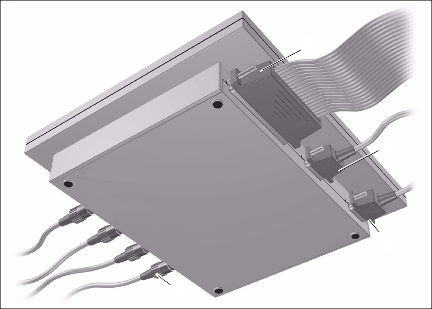
Fig. 2 - 2 Axis tester – bottom view
M Connection for ribbon cable
Connection on the axis tester: 37-pin sub-D connector
Connection on the axis controller:
– 37-pin sub-D connector for S-20/23/25/F4/F5 and HS-50 machines with A361 or A362 axis
controllers
– 25-pin sub-D connector for S-15/F3, G and wafflepack changer machines with A360 axis
controllers
An adapter is attached to the ribbon cable in order to connect the 25-pin axis controller.
The axis controller supplies the
+ 5 VDC ± 5 % and
± 15 VDC ± 5 %
operating voltages to the axis tester via the 37-pin ribbon cable.
N 9-pin sub-D connector for the CAN bus cable, e.g. for connecting CAN bus-controlled boards
in the placement machine (transmission speed 128 kBaud to 1 Mbaud, impedance 120 Ohm).
O 9-pin sub-D connector for the serial interface cable (V24), e.g. for connecting an external PC
(max. transmission speed 188 kBaud).
P Four BNC sockets, impedance 50 Ohm
The sockets can be assigned as required with the following signals:
M
N
O
P
Handbuch für das Achsprüfgerät / Axis Tester Manual SIPLACE Axis Tester
3 Package Ausgabe 08/2003 Edition
50
– Track signal A or B TTL level, max. 5 V
– Zero pulse TTL level t
min
= 1 ìsec
– End signal TTL level t
min
> 10 msec
– Trigger TTL level t
min
> 10 msec
– Counting error TTL level, trigger signal from counting error sensor for the
oscilloscope
–V
setpoint
± 10 V, analog signal, R
i
= 10 kOhm
– Force ± 10 V analog signal, R
i
= 10 kOhm
–V
REG
(total current) ± 10 V analog signal, R
i
= 10 kOhm
– Position deviation ± 10 V analog signal; the signal is generated internally in the axis
tester.
3 Package
The complete SIPLACE axis tester, part no. 03002801-01, is supplied with the following compo-
nents:
– SIPLACE Axis Tester, part no. 03000761-01
– Test cable A361 ... A363 (length 150 cm), with 37-pin plug and 37-pin socket for connecting to
the axis controllers of S2x, F4/F5 and HS placement machines,
part no. 03002803-01
– CAN bus cable, part no. 00349679-03
– RS232 C cable, part no. 03002804-01
– Manual for axis tester, part no. 00193370-01
– Optional: SAT - KSP A360 adapter for connecting to the KSP A360 axis controller of S15, F3
and G machines and wafflepack changers, part no. 003002874-01
4 Axis diagnostic equipment
– SITEST program and operating instructions for the placement machine
– Setting instructions for the placement machine

SIPLACE Axis Tester Handbuch für das Achsprüfgerät / Axis Tester Manual
Ausgabe 08/2003 Edition 5 Safety instructions
51
5 Safety instructions
WARNING 5
Only SIPLACE engineers or appropriately qualified personnel may make settings and carry out
diagnostic or troubleshooting work on the axis systems. The same applies to running and using
the SITEST program.
Æ Always follow the accident prevention regulations applicable in your country, particularly EN
60204.
Æ Press the emergency stop button before connecting the axis tester.
Æ Only appropriately trained and qualified personnel may set the key switch to set-up mode (‘I’).
During operation, do not turn the key switch to the ‘I’ position (set-up mode) unless you are
prompted to do so in the instructions or in the station software dialog.
Æ NEVER move your head or arms into the gantry travel range while the station is switched on.
Æ Protective devices must not be modified. In particular, circuit-breakers must not be bypassed
and protective devices must not be removed.
WARNING
To avoid damaging the placement head or glue dispensing unit, always observe the following
points when moving the gantry: 5
– NEVER move the gantry by pushing against the placement head or glue dispenser with your
hands.
– NEVER move the gantry while the Z axis is lowered.