00193370-0202.pdf - 第51页
SIPLACE Axis T est er Handbuch für das Achsprüfgerät / Axis T est er Manual Ausgabe 08/2003 Edition 5 Safety instructions 51 5 Safety instructions W A RNING 5 Only S IPLACE engineers or appropriate ly qualifie d personne…
Handbuch für das Achsprüfgerät / Axis Tester Manual SIPLACE Axis Tester
3 Package Ausgabe 08/2003 Edition
50
– Track signal A or B TTL level, max. 5 V
– Zero pulse TTL level t
min
= 1 ìsec
– End signal TTL level t
min
> 10 msec
– Trigger TTL level t
min
> 10 msec
– Counting error TTL level, trigger signal from counting error sensor for the
oscilloscope
–V
setpoint
± 10 V, analog signal, R
i
= 10 kOhm
– Force ± 10 V analog signal, R
i
= 10 kOhm
–V
REG
(total current) ± 10 V analog signal, R
i
= 10 kOhm
– Position deviation ± 10 V analog signal; the signal is generated internally in the axis
tester.
3 Package
The complete SIPLACE axis tester, part no. 03002801-01, is supplied with the following compo-
nents:
– SIPLACE Axis Tester, part no. 03000761-01
– Test cable A361 ... A363 (length 150 cm), with 37-pin plug and 37-pin socket for connecting to
the axis controllers of S2x, F4/F5 and HS placement machines,
part no. 03002803-01
– CAN bus cable, part no. 00349679-03
– RS232 C cable, part no. 03002804-01
– Manual for axis tester, part no. 00193370-01
– Optional: SAT - KSP A360 adapter for connecting to the KSP A360 axis controller of S15, F3
and G machines and wafflepack changers, part no. 003002874-01
4 Axis diagnostic equipment
– SITEST program and operating instructions for the placement machine
– Setting instructions for the placement machine

SIPLACE Axis Tester Handbuch für das Achsprüfgerät / Axis Tester Manual
Ausgabe 08/2003 Edition 5 Safety instructions
51
5 Safety instructions
WARNING 5
Only SIPLACE engineers or appropriately qualified personnel may make settings and carry out
diagnostic or troubleshooting work on the axis systems. The same applies to running and using
the SITEST program.
Æ Always follow the accident prevention regulations applicable in your country, particularly EN
60204.
Æ Press the emergency stop button before connecting the axis tester.
Æ Only appropriately trained and qualified personnel may set the key switch to set-up mode (‘I’).
During operation, do not turn the key switch to the ‘I’ position (set-up mode) unless you are
prompted to do so in the instructions or in the station software dialog.
Æ NEVER move your head or arms into the gantry travel range while the station is switched on.
Æ Protective devices must not be modified. In particular, circuit-breakers must not be bypassed
and protective devices must not be removed.
WARNING
To avoid damaging the placement head or glue dispensing unit, always observe the following
points when moving the gantry: 5
– NEVER move the gantry by pushing against the placement head or glue dispenser with your
hands.
– NEVER move the gantry while the Z axis is lowered.
Handbuch für das Achsprüfgerät / Axis Tester Manual SIPLACE Axis Tester
6 Structure of the user interface Ausgabe 08/2003 Edition
52
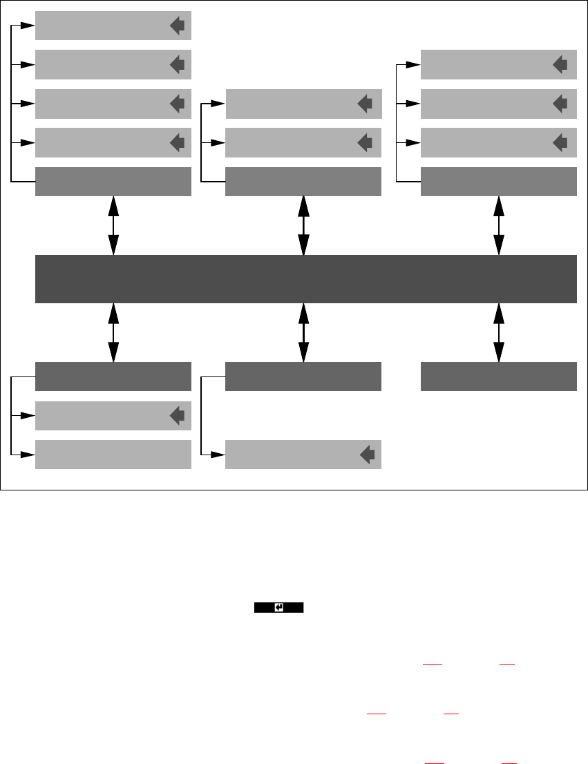
6 Structure of the user interface
6.1 Main menu
Fig. 6 - 1 Main menu of the user interface
The main menu is called from the axis tester start-up page. A window with the following menu op-
tions appears on screen:
–Quit
Press this button and then RETURN ( ) to close the main menu window.
– Configuration
The structure of the “Configuration” menu can be found in section 6.2
on page 54.
– Machine
The structure of the “Machine” menu is shown in section 6.3
on page 55.
– System control
The structure of the “System control” menu is explained in section 6.4
on page 56.
0DLQPHQX
6KXWGRZQ $ERXW
6\VWHPFRQWURO
&RQILJXUDWLRQ
0DFKLQH
Settings
User control
Display
Panel
Config unit
F machine
HS machine
Shutdown computer:
Shutdown computer: Yes
4XLW
Start-up window
Ports
S machine