00193370-0202.pdf - 第73页
SIPLACE Axis T est er Handbuch für das Achsprüfgerät / Axis T est er Manual Ausgabe 08/2003 Edition 8 Using the menus 73 Fig. 8 - 31 Setting markers T1 and T2 for the plot area Æ Us e and to move marke r T1. Use and to m…
Handbuch für das Achsprüfgerät / Axis Tester Manual SIPLACE Axis Tester
8 Using the menus Ausgabe 08/2003 Edition
72
Æ Select this option if you wish to test the axis in continuous operation.
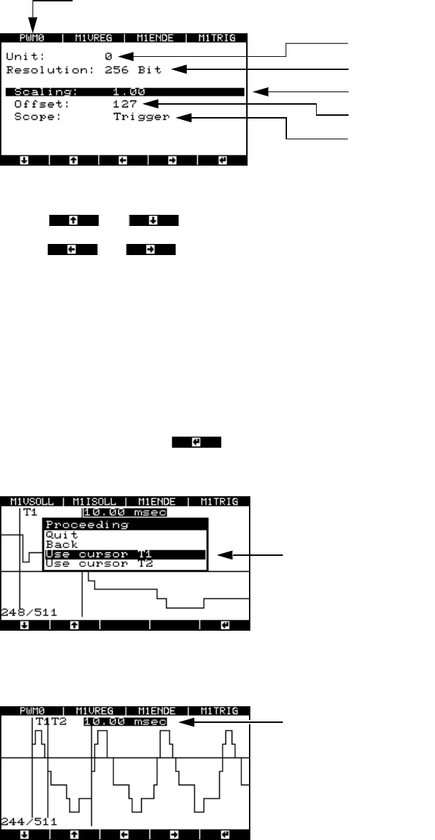
Fig. 8 - 29 Parameter display for the pulse width-modulated signal
Use the and cursor keys to select the parameters.
Use the and cursor keys to increase or reduce numerical values or select the
trigger signal.
8.4.3.4 Analyzing the positioning movement using FFT (“Start FFT” menu)
To provide further details for the analysis, we plan to output the positioning movement as a spec-
trum using the FFT.
8.4.3.5 Outputting to a plotter (“Start plot” menu)
Æ Select “Start plot” and press .
The window for selecting the time range appears.
Fig. 8 - 30 Menu for selecting the plot area
Æ Select marker T1.
Multiplexer output
Resolution
Scaling factor
Zero line offset in digits
Starting edge:
Trigger signal (A361 or higher) or en
d
signal (A360)
PWM0 signal output (top axis controller) at BNC1.
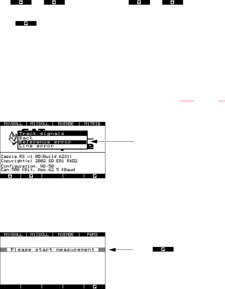
Time marker T1 and time marker
T2 for determining the time win-
dow
Time window for the selected plot area
SIPLACE Axis Tester Handbuch für das Achsprüfgerät / Axis Tester Manual
Ausgabe 08/2003 Edition 8 Using the menus
73
Fig. 8 - 31 Setting markers T1 and T2 for the plot area
Æ Use and to move marker T1. Use and to move the zero line
up or down.
Æ Press to confirm your settings.
Æ Set marker T2 as described for marker 1.
Æ Select "Quit". The numerical value of the time window is output to the plotter.
8.4.4 “Track signal” menu
This menu is designed to help you analyze and troubleshoot track signals.
Æ Select the “Track signals” option from the “Properties” menu (see Fig. 8 - 23 on page 69).
The following window appears.
Fig. 8 - 32 “Track signals” menu, “Reference error”
8.4.4.1 Checking track signals for zero pulse errors
Æ Select the “Reference error” menu option.
The window for starting the measurement appears.
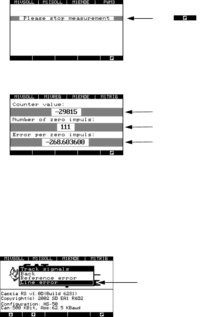
Fig. 8 - 33 Starting the measurement to identify zero pulse errors
Æ Turn the axis either manually or using the SITEST program. Then return it to the starting point
and stop the measurement.
Menu for testing the zero pulses
Press to start the measuremen
t.
Handbuch für das Achsprüfgerät / Axis Tester Manual SIPLACE Axis Tester
8 Using the menus Ausgabe 08/2003 Edition
74
Fig. 8 - 34 Stopping the measurement to identify zero pulse errors
The result appears in the next window.
Fig. 8 - 35 Result of the zero pulse measurement
Ideally, the counter value should read 0 since the forward and backward movements were
identical. In this case, a 0 will also be output for the “Error per zero impulse” value.
If the counter value is other than 0, then counting errors have occurred. A minus sign before
the counter value means that more zero pulses were measured during the backward move-
ment than during the forward movement. In this case, a value other than 0 will again be output
for “Error per zero impulse”.
8.4.4.2 Checking track signals for errors
Fig. 8 - 36 “Track signals” menu, “Line error”
Æ Select the “Line error” option from the “Track signals” menu.
The window for selecting the display mode appears.
Press to stop the measuremen
t.
Counter value
Number of measured zero pulses
Counting error per zero pulse
Menu for testing the track signals